How to Use ov7670: Examples, Pinouts, and Specs
Introduction
The OV7670 is a low-cost CMOS image sensor capable of capturing video and still images with a VGA resolution of 640x480 pixels. It is widely used in embedded systems, robotics, and IoT applications for image processing tasks. The sensor is compact, power-efficient, and supports various output formats, making it a popular choice for projects involving computer vision, object detection, and video streaming.
Explore Projects Built with ov7670
Explore Projects Built with ov7670
Common Applications
- Robotics: Object detection and navigation
- IoT devices: Image capture and video streaming
- Embedded systems: Basic computer vision tasks
- Security systems: Low-cost surveillance cameras
- Educational projects: Learning image processing and interfacing with microcontrollers
Technical Specifications
The OV7670 sensor is designed to provide high-quality image capture while maintaining low power consumption. Below are its key technical details:
Key Specifications
| Parameter | Value |
|---|---|
| Resolution | VGA (640x480 pixels) |
| Pixel Size | 3.6 µm x 3.6 µm |
| Maximum Frame Rate | 30 fps (frames per second) |
| Output Format | YUV, RGB, or RAW Bayer |
| Operating Voltage | 2.5V to 3.0V (core), 3.3V (I/O) |
| Power Consumption | ~60 mW |
| Lens Size | 1/6 inch |
| Field of View (FOV) | 25° to 60° (depending on lens) |
| Communication Interface | SCCB (similar to I2C) |
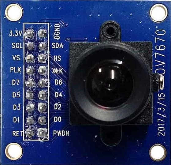
Pin Configuration
The OV7670 module typically comes with a 10-pin interface. Below is the pinout and description:
| Pin Name | Pin Number | Description |
|---|---|---|
| GND | 1 | Ground |
| VCC | 2 | Power supply (3.3V) |
| SCL | 3 | SCCB clock line (similar to I2C SCL) |
| SDA | 4 | SCCB data line (similar to I2C SDA) |
| VSYNC | 5 | Vertical sync signal |
| HREF | 6 | Horizontal reference signal |
| PCLK | 7 | Pixel clock output |
| XCLK | 8 | External clock input (required for operation) |
| D0-D7 | 9-16 | Data output pins (8-bit parallel data) |
| RESET | 17 | Reset pin (active low) |
Usage Instructions
The OV7670 sensor requires an external clock signal (XCLK) to operate, which can be generated using a microcontroller or an external oscillator. It communicates using the SCCB protocol (similar to I2C) for configuration and outputs image data through an 8-bit parallel interface.
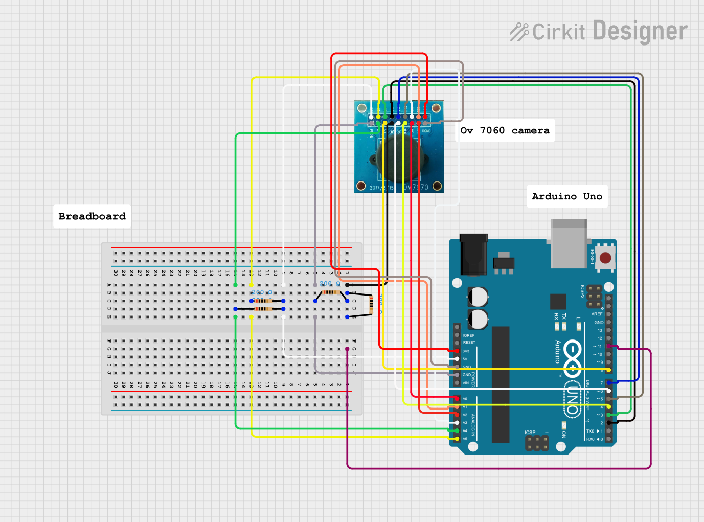
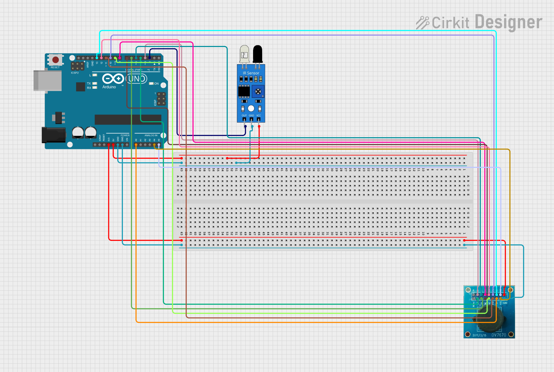
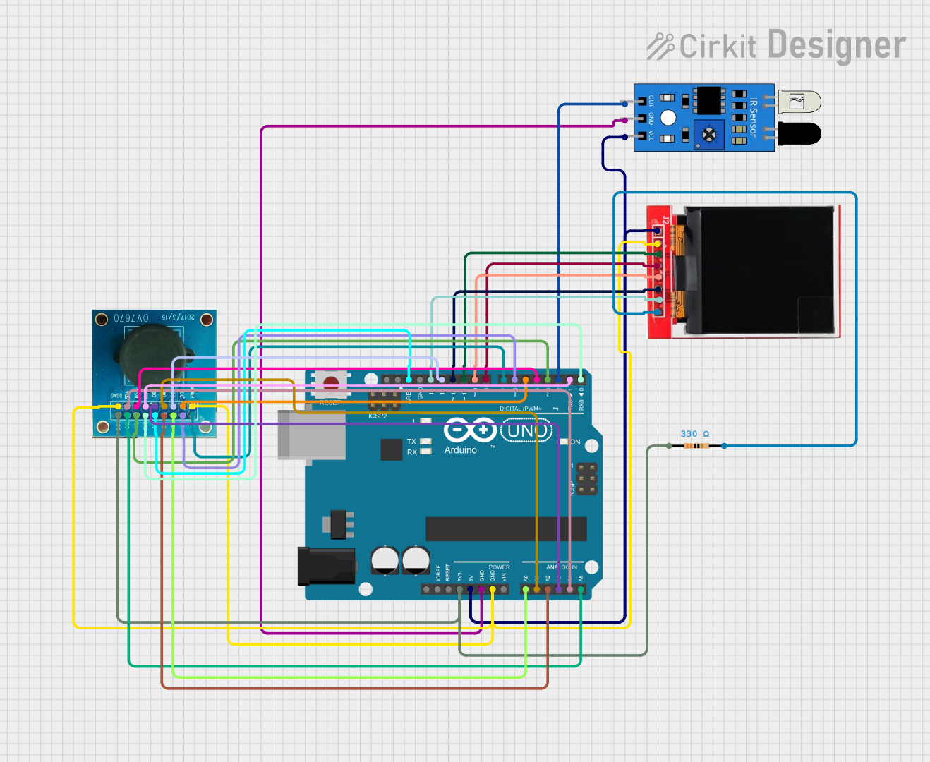
Connecting the OV7670 to an Arduino UNO
Below is a basic guide to connect the OV7670 to an Arduino UNO:
- Power Supply: Connect the VCC pin to the 3.3V pin on the Arduino and GND to ground.
- Clock Signal: Use a PWM pin on the Arduino to generate the required XCLK signal (typically 8 MHz).
- SCCB Communication: Connect the SDA and SCL pins of the OV7670 to the Arduino's A4 (SDA) and A5 (SCL) pins, respectively.
- Data Pins: Connect the D0-D7 pins to digital pins on the Arduino for data capture.
- Other Pins: Connect VSYNC, HREF, and PCLK to additional digital pins for synchronization.
Sample Arduino Code
The following code demonstrates how to initialize the OV7670 and generate the XCLK signal using an Arduino UNO:
// OV7670 Initialization Example
// Generates an 8 MHz clock signal on pin 9 for the OV7670 XCLK input

#include <Wire.h> // Include Wire library for SCCB communication

#define OV7670_SDA A4 // SDA pin connected to Arduino A4
#define OV7670_SCL A5 // SCL pin connected to Arduino A5

void setup() {
  pinMode(9, OUTPUT); // Set pin 9 as output for XCLK
  setupXCLK();        // Generate 8 MHz clock signal
  Wire.begin();       // Initialize I2C communication

  // Example: Write to OV7670 registers (replace with actual register values)
  writeRegister(0x12, 0x80); // Reset the OV7670
  delay(100);                // Wait for reset to complete
  writeRegister(0x12, 0x14); // Set to RGB mode
}

void loop() {
  // Main loop can be used to capture and process image data
}

// Function to generate an 8 MHz clock signal on pin 9
void setupXCLK() {
  TCCR1A = 0; // Clear Timer/Counter Control Register A
  TCCR1B = 0; // Clear Timer/Counter Control Register B
  TCNT1 = 0;  // Clear Timer/Counter Register
  TCCR1A = _BV(COM1A0); // Toggle OC1A on Compare Match
  TCCR1B = _BV(WGM12) | _BV(CS10); // CTC mode, no prescaler
  OCR1A = 1; // Set output compare register for 8 MHz
}

// Function to write to OV7670 registers via SCCB
void writeRegister(uint8_t reg, uint8_t value) {
  Wire.beginTransmission(0x42 >> 1); // OV7670 SCCB address
  Wire.write(reg);                   // Register address
  Wire.write(value);                 // Register value
  Wire.endTransmission();            // End transmission
}
Important Considerations
- The OV7670 requires precise timing for the XCLK signal. Ensure the clock frequency matches the sensor's requirements.
- The SCCB protocol is similar to I2C but may require slight modifications in timing for reliable communication.
- The OV7670 outputs raw image data, which may need to be processed or converted into a usable format (e.g., BMP or JPEG).
Troubleshooting and FAQs
Common Issues
No Image Output:
- Ensure the XCLK signal is being generated and connected to the OV7670.
- Verify the SCCB communication is working by reading/writing to registers.
Distorted or Noisy Image:
- Check the power supply voltage (3.3V) and ensure it is stable.
- Verify the lens is clean and properly focused.
SCCB Communication Fails:
- Confirm the SDA and SCL connections are correct.
- Use pull-up resistors (4.7kΩ) on the SDA and SCL lines if necessary.
Incorrect Image Format:
- Verify the register settings for the desired output format (e.g., RGB, YUV).
Tips for Troubleshooting
- Use an oscilloscope to verify the XCLK, PCLK, and data signals.
- Start with a simple configuration (e.g., RGB mode) before attempting advanced features.
- Refer to the OV7670 datasheet for detailed register descriptions and configuration options.
By following this documentation, you should be able to successfully integrate the OV7670 into your projects and troubleshoot common issues effectively.