How to Use STM32f407VET6: Examples, Pinouts, and Specs
Introduction
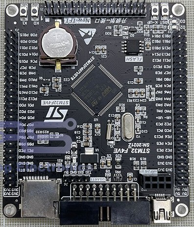
The STM32F407VET6 is a high-performance ARM Cortex-M4 32-bit microcontroller. It features 512 KB of Flash memory, 192 KB of RAM, and a wide range of peripherals, including USB, CAN, and Ethernet interfaces. This microcontroller is suitable for various embedded applications, such as industrial control, consumer electronics, and communication systems.
Explore Projects Built with STM32f407VET6

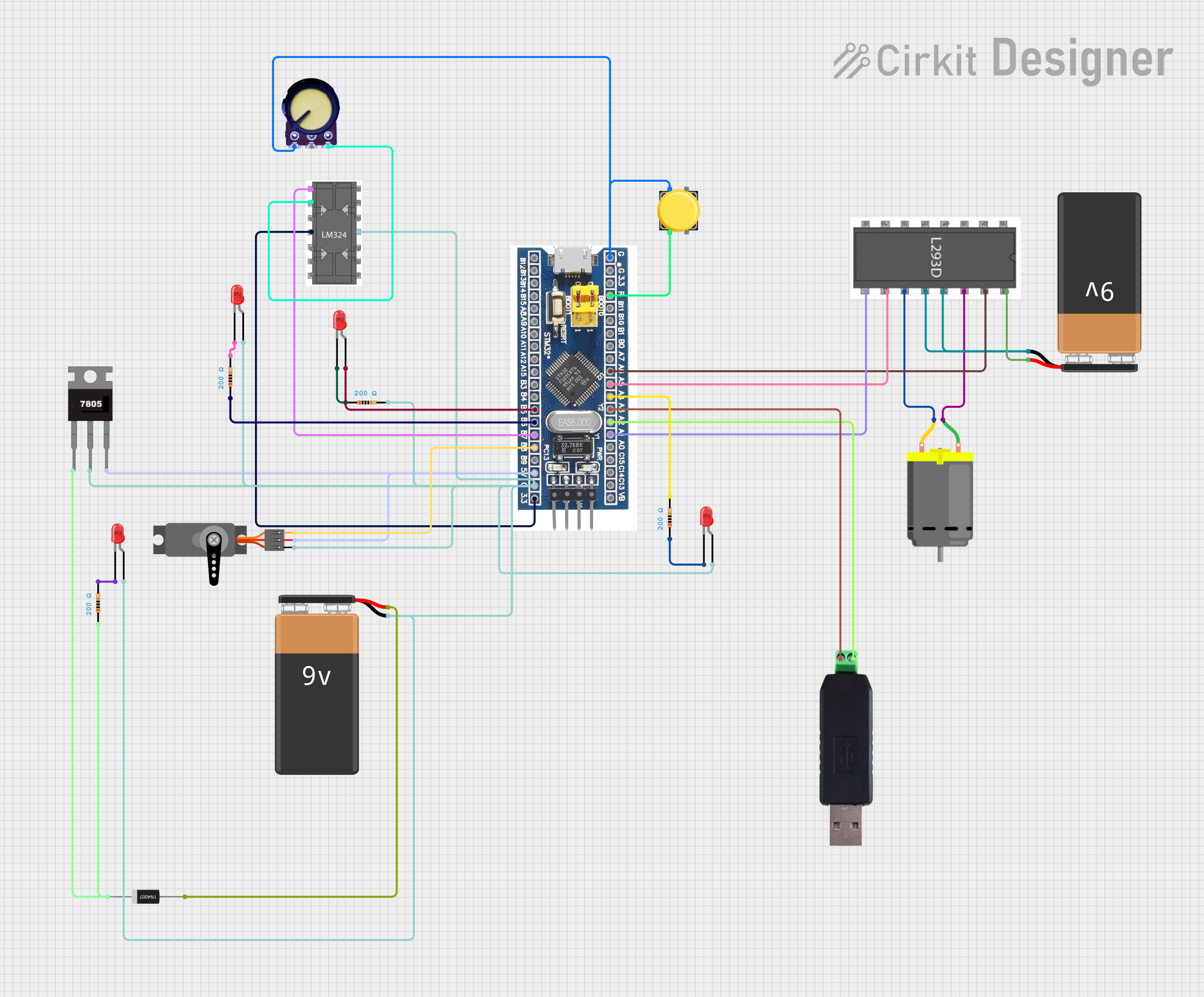
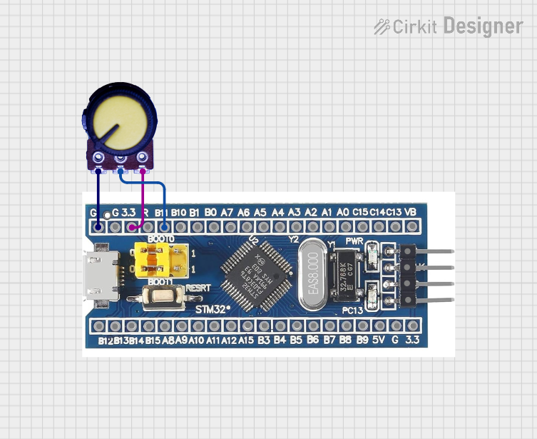

Explore Projects Built with STM32f407VET6
Technical Specifications
Key Technical Details
| Parameter | Value |
|---|---|
| Core | ARM Cortex-M4 |
| Flash Memory | 512 KB |
| RAM | 192 KB |
| Operating Voltage | 1.8V to 3.6V |
| Clock Speed | Up to 168 MHz |
| GPIO Pins | 82 |
| Communication | USB, CAN, Ethernet, I2C, SPI, UART |
| Timers | 14 (including advanced control timers) |
| ADC | 3 (12-bit, up to 24 channels) |
| DAC | 2 (12-bit) |
| Operating Temperature | -40°C to 85°C |
Pin Configuration and Descriptions
| Pin Number | Pin Name | Description |
|---|---|---|
| 1 | VDD | Power Supply |
| 2 | VSS | Ground |
| 3 | PA0 | GPIO Port A Pin 0 / ADC_IN0 / WKUP |
| 4 | PA1 | GPIO Port A Pin 1 / ADC_IN1 |
| 5 | PA2 | GPIO Port A Pin 2 / ADC_IN2 / USART2_TX |
| 6 | PA3 | GPIO Port A Pin 3 / ADC_IN3 / USART2_RX |
| ... | ... | ... |
| 100 | PB15 | GPIO Port B Pin 15 / SPI2_MOSI |
Usage Instructions
How to Use the Component in a Circuit
- Power Supply: Connect the VDD pin to a 3.3V power supply and the VSS pin to ground.
- Clock Configuration: Use an external 8 MHz crystal oscillator connected to the OSC_IN and OSC_OUT pins for accurate clocking.
- Reset: Connect a pull-up resistor (10kΩ) to the NRST pin to ensure proper reset functionality.
- Programming Interface: Use the SWD (Serial Wire Debug) interface for programming and debugging. Connect the SWDIO and SWCLK pins to the corresponding pins on the programmer.
Important Considerations and Best Practices
- Decoupling Capacitors: Place decoupling capacitors (0.1µF) close to the VDD pins to filter out noise.
- Ground Plane: Use a solid ground plane in your PCB design to reduce electromagnetic interference.
- Unused Pins: Configure unused GPIO pins as analog inputs to reduce power consumption.
- Boot Configuration: Set the BOOT0 and BOOT1 pins according to the desired boot mode (e.g., Flash memory, system memory).
Example Code for Arduino UNO
#include <Wire.h>

// Define the I2C address of the STM32F407VET6
#define STM32_I2C_ADDRESS 0x68

void setup() {
  // Initialize I2C communication
  Wire.begin();
  Serial.begin(9600);
}

void loop() {
  // Request data from the STM32F407VET6
  Wire.beginTransmission(STM32_I2C_ADDRESS);
  Wire.write(0x00); // Register address to read from
  Wire.endTransmission();

  Wire.requestFrom(STM32_I2C_ADDRESS, 2); // Request 2 bytes of data

  if (Wire.available() == 2) {
    int data = Wire.read() << 8 | Wire.read();
    Serial.print("Data: ");
    Serial.println(data);
  }

  delay(1000); // Wait for 1 second before next read
}
Troubleshooting and FAQs
Common Issues Users Might Face
Microcontroller Not Responding:
- Solution: Check the power supply and ensure that the VDD and VSS pins are properly connected. Verify the clock configuration and reset circuitry.
Programming Failure:
- Solution: Ensure that the SWD interface is correctly connected. Check the BOOT0 and BOOT1 pin settings. Verify that the programmer is functioning correctly.
Peripheral Communication Issues:
- Solution: Double-check the pin configurations and connections for the specific peripheral (e.g., I2C, SPI). Ensure that the peripheral initialization code is correct.
FAQs
Q1: Can I use the STM32F407VET6 with a 5V power supply?
- A1: No, the STM32F407VET6 operates within a voltage range of 1.8V to 3.6V. Using a 5V power supply can damage the microcontroller.
Q2: How do I configure the GPIO pins?
- A2: GPIO pins can be configured using the STM32CubeMX software, which generates initialization code for the STM32F407VET6.
Q3: What is the maximum clock speed of the STM32F407VET6?
- A3: The maximum clock speed is 168 MHz.
Q4: How do I update the firmware on the STM32F407VET6?
- A4: Firmware can be updated using the SWD interface or via USB using the DFU (Device Firmware Upgrade) mode.
This documentation provides a comprehensive overview of the STM32F407VET6 microcontroller, including its technical specifications, usage instructions, and troubleshooting tips. Whether you are a beginner or an experienced user, this guide will help you effectively utilize the STM32F407VET6 in your embedded applications.