How to Use 12V to 5V USB-C Connection: Examples, Pinouts, and Specs
Introduction
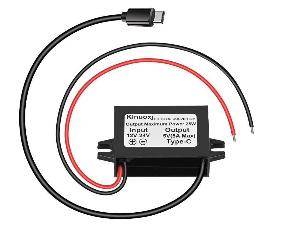
The 12V to 5V USB-C Connection is a power conversion module designed to step down a 12V input voltage to a stable 5V output. This module is ideal for powering USB-C devices such as smartphones, tablets, single-board computers, and other peripherals that require a 5V input. Its compact design and high efficiency make it a popular choice for automotive, DIY electronics, and embedded systems applications.
Explore Projects Built with 12V to 5V USB-C Connection


Explore Projects Built with 12V to 5V USB-C Connection
Common Applications and Use Cases
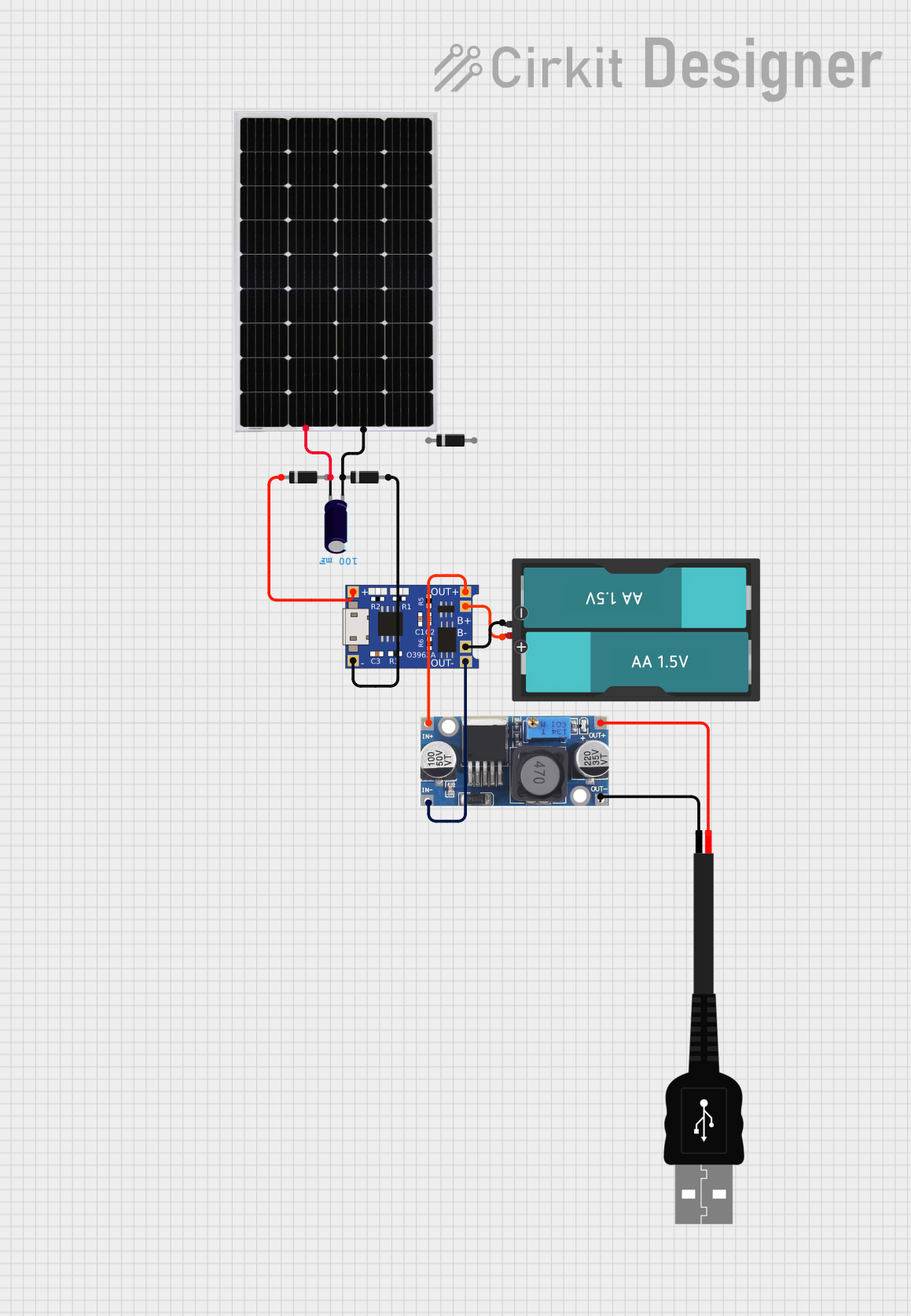
- Powering USB-C devices from a 12V car battery or power supply
- Integrating USB-C power delivery into custom electronics projects
- Providing a stable 5V output for single-board computers like Raspberry Pi
- Charging USB-C devices in automotive or off-grid setups
Technical Specifications
Below are the key technical details and pin configuration for the 12V to 5V USB-C Connection module:
Key Technical Details
| Parameter | Value |
|---|---|
| Input Voltage Range | 9V to 14V |
| Output Voltage | 5V (±0.1V) |
| Maximum Output Current | 3A |
| Efficiency | Up to 92% |
| Connector Type | USB-C Female |
| Operating Temperature | -20°C to 60°C |
| Dimensions | 25mm x 20mm x 10mm |
| Protection Features | Overcurrent, Overvoltage, |
| Short Circuit Protection |
Pin Configuration and Descriptions
| Pin Name | Description |
|---|---|
| VIN+ | Positive input terminal for 12V power supply |
| VIN- | Negative input terminal (ground) for 12V power supply |
| USB-C VBUS | 5V output terminal connected to the USB-C VBUS pin |
| USB-C GND | Ground terminal connected to the USB-C GND pin |
Usage Instructions
How to Use the Component in a Circuit
- Connect the Input Voltage:
- Attach the VIN+ pin to the positive terminal of a 12V power source.
- Connect the VIN- pin to the ground terminal of the same power source.
- Connect the USB-C Device:
- Plug the USB-C device into the module's USB-C female connector.
- Power On:
- Turn on the 12V power source. The module will automatically step down the voltage to 5V and supply it to the USB-C device.
Important Considerations and Best Practices
- Ensure the input voltage is within the specified range (9V to 14V). Exceeding this range may damage the module.
- Verify that the connected USB-C device does not draw more than 3A of current.
- Use proper heat dissipation methods if the module operates at high currents for extended periods.
- Avoid shorting the output terminals to prevent damage to the module and connected devices.
Example: Using with an Arduino UNO
The 12V to 5V USB-C Connection module can be used to power an Arduino UNO via its USB port. Below is an example of how to connect the module:
- Connect the VIN+ and VIN- pins of the module to a 12V power source.
- Plug the USB-C cable from the module into the Arduino UNO's USB port.
- Power on the 12V source, and the Arduino UNO will receive a stable 5V supply.
Arduino Code Example
If you are using the Arduino UNO with a USB-C powered sensor, here is a simple code snippet to read data from the sensor:
// Example code to read data from a USB-C powered sensor
// connected to an Arduino UNO via the 12V to 5V USB-C module.

const int sensorPin = A0; // Analog pin connected to the sensor
int sensorValue = 0;      // Variable to store the sensor reading

void setup() {
  Serial.begin(9600); // Initialize serial communication at 9600 baud
  pinMode(sensorPin, INPUT); // Set the sensor pin as input
}

void loop() {
  sensorValue = analogRead(sensorPin); // Read the sensor value
  Serial.print("Sensor Value: ");      // Print the sensor value to the serial monitor
  Serial.println(sensorValue);
  delay(1000); // Wait for 1 second before the next reading
}
Troubleshooting and FAQs
Common Issues and Solutions
No Output Voltage:
- Cause: Input voltage is outside the specified range.
- Solution: Verify that the input voltage is between 9V and 14V.
Device Not Charging:
- Cause: The connected device requires more than 3A of current.
- Solution: Ensure the device's current requirements are within the module's limits.
Module Overheating:
- Cause: Prolonged operation at maximum current without proper ventilation.
- Solution: Use a heatsink or improve airflow around the module.
Short Circuit Protection Triggered:
- Cause: Output terminals are shorted.
- Solution: Disconnect the power source, resolve the short circuit, and reconnect.
FAQs
Q: Can this module be used with a 24V power source?
A: No, the module is designed for input voltages between 9V and 14V. Using a 24V source may damage the module.
Q: Is the module compatible with USB-C Power Delivery (PD)?
A: No, this module provides a fixed 5V output and does not support USB-C PD negotiation.
Q: Can I use this module to power a Raspberry Pi?
A: Yes, the module can provide a stable 5V output suitable for powering a Raspberry Pi via its USB-C power input. Ensure the current requirements of the Raspberry Pi and connected peripherals do not exceed 3A.