Cirkit Designer Logo
Cirkit Designer
Your all-in-one circuit design IDE
Home / 
Component Documentation

How to Use Adafruit AW9523: Examples, Pinouts, and Specs

Image of Adafruit AW9523
Cirkit Designer LogoDesign with Adafruit AW9523 in Cirkit Designer

Introduction

The Adafruit AW9523 is a versatile I2C GPIO expander that significantly increases the number of GPIO pins available for use with microcontrollers such as the Arduino UNO. This module is particularly useful in projects where a large number of sensors, LEDs, or other peripherals need to be controlled, and the microcontroller itself does not have enough pins. The AW9523 is capable of handling 16 additional GPIOs, each of which can be individually set as an input or output.

Explore Projects Built with Adafruit AW9523

Use Cirkit Designer to design, explore, and prototype these projects online. Some projects support real-time simulation. Click "Open Project" to start designing instantly!
Battery-Powered Smart Sensor Hub with Adafruit QT Py RP2040
Image of wearable final: A project utilizing Adafruit AW9523 in a practical application
This circuit features an Adafruit QT Py RP2040 microcontroller interfaced with an APDS9960 proximity sensor, an MPU6050 accelerometer and gyroscope, and an OLED display via I2C communication. It also includes a buzzer controlled by the microcontroller and is powered by a 3.7V LiPo battery with a toggle switch for power control.
Cirkit Designer LogoOpen Project in Cirkit Designer
Arduino UNO-Based Motion-Activated LED Strip with MPU6050 and Battery Power
Image of GG: A project utilizing Adafruit AW9523 in a practical application
This circuit features an Arduino UNO microcontroller interfaced with three MPU6050 accelerometer and gyroscope sensors for motion detection and three WS2815 LED strips for visual output. The system is powered by a Li-ion battery and includes a voltage regulator for stable power supply, with the Arduino controlling the sensors and LED strips via I2C and digital pins.
Cirkit Designer LogoOpen Project in Cirkit Designer
Arduino Mega 2560 Multi-Sensor Data Logger with I2C Multiplexer
Image of Gesamt Schaltplan: A project utilizing Adafruit AW9523 in a practical application
This circuit uses an Arduino Mega 2560 to interface with multiple sensors, including an Adafruit ADXL326 accelerometer, a pressure transducer, and two MLX90614 IR temperature sensors connected via an Adafruit TCA9548A I2C multiplexer. The Arduino reads data from these sensors and outputs the values to the Serial Monitor.
Cirkit Designer LogoOpen Project in Cirkit Designer
Arduino Nano Controlled Smart Relay with APDS-9960 Gesture Sensor
Image of contactless smart switch: A project utilizing Adafruit AW9523 in a practical application
This circuit features an Arduino Nano microcontroller interfaced with an Adafruit APDS-9960 sensor and a 2-channel relay module. The APDS-9960 sensor, which is capable of gesture detection, is connected to the Arduino via I2C communication lines (SCL, SDA) and powered by the Arduino's 3.3V output. The relay module is controlled by the Arduino through a digital pin (D7) and is used to switch an AC-powered bulb on and off, with the relay's common (COM) terminal connected to the AC source and the normally open (NO1) terminal connected to the bulb.
Cirkit Designer LogoOpen Project in Cirkit Designer

Explore Projects Built with Adafruit AW9523

Use Cirkit Designer to design, explore, and prototype these projects online. Some projects support real-time simulation. Click "Open Project" to start designing instantly!
Image of wearable final: A project utilizing Adafruit AW9523 in a practical application
Battery-Powered Smart Sensor Hub with Adafruit QT Py RP2040
This circuit features an Adafruit QT Py RP2040 microcontroller interfaced with an APDS9960 proximity sensor, an MPU6050 accelerometer and gyroscope, and an OLED display via I2C communication. It also includes a buzzer controlled by the microcontroller and is powered by a 3.7V LiPo battery with a toggle switch for power control.
Cirkit Designer LogoOpen Project in Cirkit Designer
Image of GG: A project utilizing Adafruit AW9523 in a practical application
Arduino UNO-Based Motion-Activated LED Strip with MPU6050 and Battery Power
This circuit features an Arduino UNO microcontroller interfaced with three MPU6050 accelerometer and gyroscope sensors for motion detection and three WS2815 LED strips for visual output. The system is powered by a Li-ion battery and includes a voltage regulator for stable power supply, with the Arduino controlling the sensors and LED strips via I2C and digital pins.
Cirkit Designer LogoOpen Project in Cirkit Designer
Image of Gesamt Schaltplan: A project utilizing Adafruit AW9523 in a practical application
Arduino Mega 2560 Multi-Sensor Data Logger with I2C Multiplexer
This circuit uses an Arduino Mega 2560 to interface with multiple sensors, including an Adafruit ADXL326 accelerometer, a pressure transducer, and two MLX90614 IR temperature sensors connected via an Adafruit TCA9548A I2C multiplexer. The Arduino reads data from these sensors and outputs the values to the Serial Monitor.
Cirkit Designer LogoOpen Project in Cirkit Designer
Image of contactless smart switch: A project utilizing Adafruit AW9523 in a practical application
Arduino Nano Controlled Smart Relay with APDS-9960 Gesture Sensor
This circuit features an Arduino Nano microcontroller interfaced with an Adafruit APDS-9960 sensor and a 2-channel relay module. The APDS-9960 sensor, which is capable of gesture detection, is connected to the Arduino via I2C communication lines (SCL, SDA) and powered by the Arduino's 3.3V output. The relay module is controlled by the Arduino through a digital pin (D7) and is used to switch an AC-powered bulb on and off, with the relay's common (COM) terminal connected to the AC source and the normally open (NO1) terminal connected to the bulb.
Cirkit Designer LogoOpen Project in Cirkit Designer

Common Applications and Use Cases

  • Expanding the number of GPIOs for microcontrollers
  • LED displays and LED matrix control
  • Sensor arrays for data collection
  • Robotics control systems
  • Home automation and IoT devices

Technical Specifications

Key Technical Details

  • Supply Voltage (VCC): 2.3V to 5.5V
  • I2C Interface Voltage: 1.8V to 5.5V
  • Output Current (per pin): Up to 25mA
  • Maximum Output Current (total): 200mA
  • Input Leakage Current (per pin): ±1µA
  • I2C Address Range: 0x58 to 0x5F (adjustable via hardware)

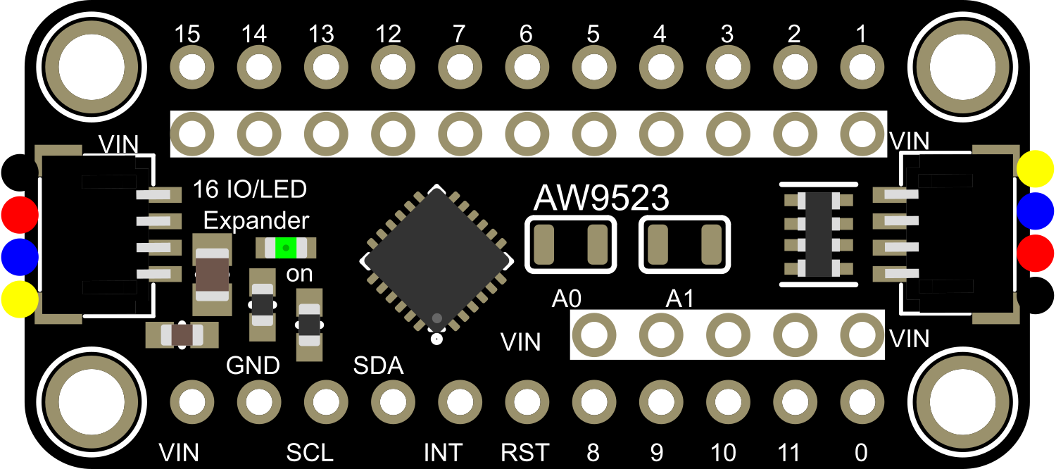
Pin Configuration and Descriptions

Pin Number Pin Name Description
1 VCC Power supply (2.3V to 5.5V)
2 SCL I2C clock signal
3 SDA I2C data signal
4 INT Interrupt output (active low)
5 ADDR I2C address selection (connect to GND or VCC)
6-21 IO0-IO15 GPIO pins (configurable as input or output)
22 GND Ground

Usage Instructions

How to Use the Component in a Circuit

  1. Powering the Module:

    • Connect the VCC pin to a power supply within the range of 2.3V to 5.5V.
    • Connect the GND pin to the ground of your power supply.
  2. Connecting to a Microcontroller:

    • Connect the SCL and SDA pins to the corresponding I2C clock and data pins on your microcontroller.
    • If necessary, use pull-up resistors on the SCL and SDA lines as per the microcontroller's I2C requirements.
  3. Setting the I2C Address:

    • The ADDR pin can be connected to GND or VCC to set the I2C address of the module. This allows up to 8 AW9523 modules to be used on the same I2C bus.
  4. Using the GPIO Pins:

    • Configure each IO pin as either an input or output using the appropriate commands in your microcontroller's code.
    • Ensure that the current draw from each IO pin does not exceed 25mA and the total current draw from all pins does not exceed 200mA.

Important Considerations and Best Practices

  • Always ensure that the power supply voltage is within the specified range to prevent damage to the module.
  • When using multiple AW9523 modules, ensure that each has a unique I2C address.
  • Avoid drawing excessive current from the GPIO pins to prevent damage and ensure reliable operation.
  • Use the interrupt pin (INT) to efficiently detect input changes on the GPIO pins without the need for constant polling.

Troubleshooting and FAQs

Common Issues Users Might Face

  • I2C Communication Failure:

    • Check connections to SCL and SDA pins.
    • Verify that pull-up resistors are correctly installed if required.
    • Ensure that the I2C address is correctly set and does not conflict with other devices on the bus.
  • Insufficient Output Current:

    • Confirm that the current draw from each IO pin and the total current draw from all pins are within limits.
  • Unresponsive GPIO Pins:

    • Double-check the pin configuration in your code to ensure pins are set to the correct mode (input or output).
    • Verify that the power supply is stable and within the specified voltage range.

Solutions and Tips for Troubleshooting

  • Use a multimeter to check for proper voltage levels and continuity in your connections.
  • Utilize the serial monitor to debug and monitor the status of the I2C communication.
  • If using multiple AW9523 modules, incrementally add one module at a time to the I2C bus to isolate issues.

FAQs

Q: Can I use the AW9523 with a 3.3V microcontroller? A: Yes, the AW9523 supports I2C interface voltages from 1.8V to 5.5V, making it compatible with both 3.3V and 5V systems.

Q: How do I change the I2C address of the module? A: The I2C address can be changed by connecting the ADDR pin to either GND or VCC. The specific address mapping can be found in the AW9523 datasheet.

Q: Can I use the interrupt pin to wake up my microcontroller from sleep mode? A: Yes, the INT pin can be used as an external interrupt to wake up microcontrollers that support this feature.

Example Code for Arduino UNO

#include <Wire.h>
#include <Adafruit_AW9523.h>

// Create AW9523 instance
Adafruit_AW9523 aw9523;

void setup() {
  Serial.begin(9600);
  // Initialize the AW9523
  if (!aw9523.begin()) {
    Serial.println("AW9523 not found");
    while (1);
  }
  Serial.println("AW9523 found!");

  // Set all pins to outputs
  for (int i = 0; i < 16; i++) {
    aw9523.pinMode(i, OUTPUT);
  }

  // Set all pins to low
  for (int i = 0; i < 16; i++) {
    aw9523.digitalWrite(i, LOW);
  }
}

void loop() {
  // Example: Toggle all pins
  for (int i = 0; i < 16; i++) {
    aw9523.digitalWrite(i, HIGH);
    delay(100);
    aw9523.digitalWrite(i, LOW);
  }
}

This example initializes the AW9523 and sets all pins as outputs. It then toggles each pin on and off in sequence. Ensure that the Adafruit AW9523 library is installed in your Arduino IDE before compiling and uploading this code to your Arduino UNO.