How to Use Sabertooth: Examples, Pinouts, and Specs
Introduction
The Sabertooth is a high-performance motor driver designed for controlling DC motors and stepper motors in robotics and automation applications. It is capable of driving motors with high current demands while maintaining precise control. The Sabertooth features advanced control algorithms, multiple operating modes, and built-in protection mechanisms, making it a reliable choice for demanding applications such as robotic arms, mobile robots, conveyor systems, and automated machinery.
Common applications include:
- Robotics (e.g., mobile robots, robotic arms)
- Automation systems
- Electric vehicles and carts
- Conveyor belts and industrial machinery
- Remote-controlled vehicles
Explore Projects Built with Sabertooth


Explore Projects Built with Sabertooth
Technical Specifications
The Sabertooth motor driver is available in various models, each with different current and voltage ratings. Below are the general specifications for a typical Sabertooth model (e.g., Sabertooth 2x25):
| Parameter | Value |
|---|---|
| Operating Voltage Range | 6V to 30V |
| Continuous Current (per channel) | 25A |
| Peak Current (per channel) | 50A |
| Control Modes | Analog, R/C, Serial, Packetized Serial |
| Motor Channels | 2 |
| PWM Frequency | 24 kHz |
| Efficiency | Up to 99% |
| Protection Features | Overcurrent, thermal, and low-voltage shutdown |
| Dimensions | 76mm x 76mm x 25mm |
| Weight | ~100g |
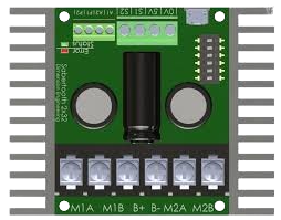
Pin Configuration and Descriptions
The Sabertooth motor driver has several input and output pins for power, motor connections, and control signals. Below is a typical pin configuration:
| Pin Name | Description |
|---|---|
| VIN | Power input for the motor driver (6V to 30V). Connect to a suitable power source. |
| GND | Ground connection for the power supply and control signals. |
| M1A, M1B | Outputs for Motor 1. Connect to the terminals of the first motor. |
| M2A, M2B | Outputs for Motor 2. Connect to the terminals of the second motor. |
| S1, S2 | Control signal inputs. Used for analog, R/C, or serial control modes. |
| 5V OUT | Regulated 5V output. Can be used to power external control circuits (max 1A). |
| DIP Switches | Used to configure operating modes and settings. |
Usage Instructions
How to Use the Sabertooth in a Circuit
- Power Supply: Connect a DC power supply (6V to 30V) to the VIN and GND pins. Ensure the power supply can provide sufficient current for the motors.
- Motor Connections: Connect the terminals of the motors to the M1A/M1B and M2A/M2B outputs.
- Control Signals: Depending on the control mode:
- For analog control, connect a potentiometer or analog signal to the S1 and S2 pins.
- For R/C control, connect the signal wires from an R/C receiver to the S1 and S2 pins.
- For serial control, connect the TX pin of a microcontroller (e.g., Arduino) to the S1 pin.
- DIP Switch Configuration: Set the DIP switches to configure the desired operating mode (refer to the Sabertooth user manual for specific settings).
- Testing: Power on the system and test the motor driver using the chosen control method.
Important Considerations and Best Practices
- Use appropriately rated motors and power supplies to avoid overloading the Sabertooth.
- Ensure proper heat dissipation by mounting the Sabertooth in a well-ventilated area or using a heatsink if necessary.
- Use fuses or circuit breakers to protect the system from overcurrent conditions.
- When using serial control, ensure the baud rate matches the Sabertooth's configuration.
- Avoid reversing the polarity of the power supply, as this can damage the motor driver.
Example: Using Sabertooth with Arduino UNO
Below is an example of controlling the Sabertooth in serial mode using an Arduino UNO:
#include <SoftwareSerial.h>

// Define the TX pin for SoftwareSerial
SoftwareSerial SabertoothSerial(10, 11); // RX, TX (RX not used in this case)

void setup() {
  SabertoothSerial.begin(9600); // Set baud rate to match Sabertooth configuration
}

void loop() {
  // Send commands to control the motors
  SabertoothSerial.write(64); // Motor 1 forward at half speed
  delay(1000);                // Run for 1 second
  SabertoothSerial.write(192); // Motor 1 reverse at half speed
  delay(1000);                // Run for 1 second
}
Note: Adjust the baud rate and commands based on your specific Sabertooth model and application.
Troubleshooting and FAQs
Common Issues and Solutions
Motors not running:
- Check the power supply voltage and ensure it is within the operating range.
- Verify the motor connections to the M1A/M1B and M2A/M2B terminals.
- Ensure the control signals are correctly configured and connected.
Overheating:
- Ensure the Sabertooth is not overloaded. Check the motor's current draw.
- Improve ventilation or add a heatsink to the Sabertooth.
Erratic motor behavior:
- Check for noise or interference in the control signals.
- Use shielded cables for signal connections if necessary.
No response in serial mode:
- Verify the baud rate and ensure it matches the Sabertooth's DIP switch settings.
- Check the TX connection from the microcontroller to the S1 pin.
FAQs
Q: Can the Sabertooth drive stepper motors?
A: Yes, the Sabertooth can drive stepper motors in certain configurations. Refer to the user manual for details on stepper motor control.
Q: Can I use the Sabertooth with a 3.3V microcontroller?
A: Yes, the Sabertooth is compatible with 3.3V and 5V logic levels for control signals.
Q: What happens if the input voltage drops below 6V?
A: The Sabertooth will enter low-voltage shutdown mode to protect the motors and the driver.
Q: Can I control the Sabertooth wirelessly?
A: Yes, you can use an R/C receiver or a wireless serial module (e.g., Bluetooth or XBee) to control the Sabertooth.