How to Use ML8511 UV Sensor Breakout: Examples, Pinouts, and Specs
Introduction
The ML8511 UV Sensor Breakout is an advanced electronic component designed to measure ultraviolet (UV) light intensity. This sensor is sensitive to UV wavelengths from 280-390 nm (UVA and UVB spectrum) and outputs an analog signal that corresponds to the UV light intensity. Common applications include detecting UV exposure in outdoor environments, monitoring UV light sources in laboratories, and integrating into wearable devices for health monitoring.
Explore Projects Built with ML8511 UV Sensor Breakout
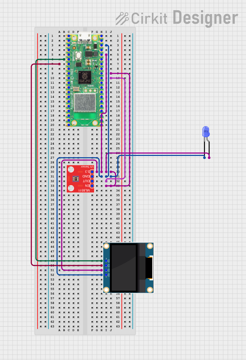
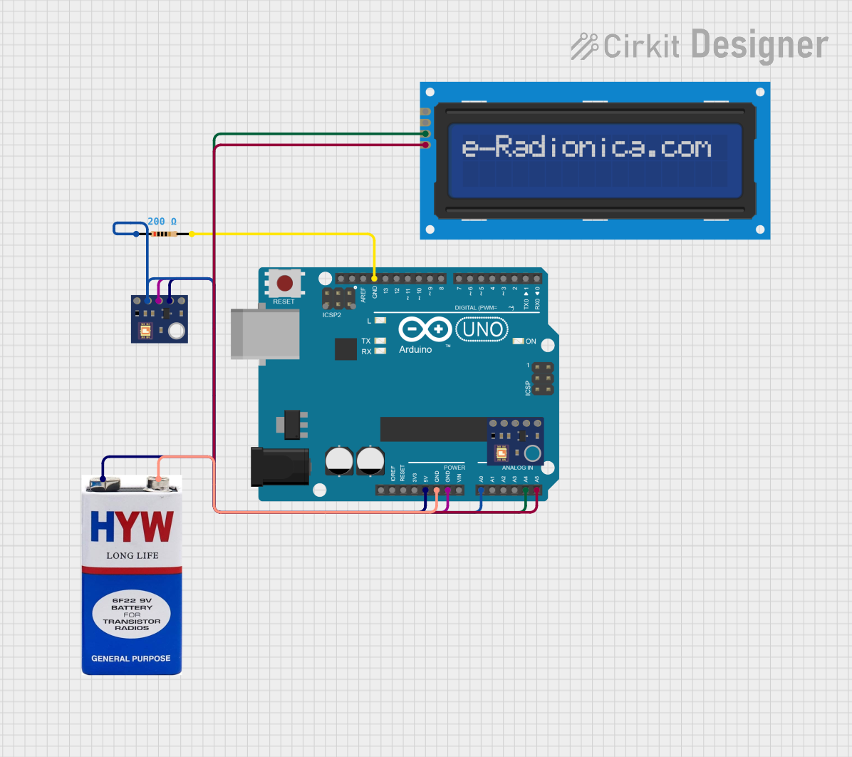
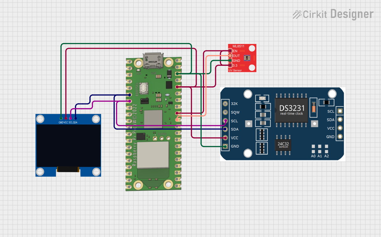
Explore Projects Built with ML8511 UV Sensor Breakout
Technical Specifications
Key Technical Details
- Supply Voltage (VCC): 2.5V to 5.5V
- Operating Current: 300 µA (typical)
- Output Voltage: 0V to 1V (linear relationship with UV intensity)
- Spectral Response: 280-390 nm (UVA and UVB)
- Response Time: Less than 500 ms
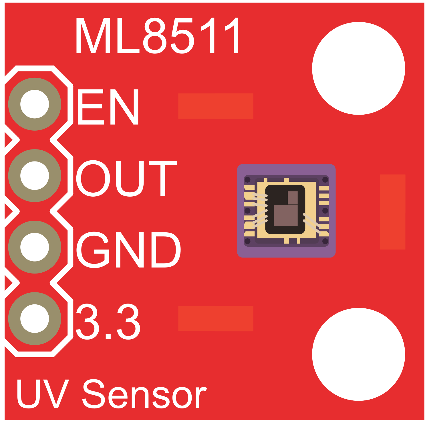
Pin Configuration and Descriptions
| Pin Number | Name | Description |
|---|---|---|
| 1 | EN | Enable pin for the sensor (active high) |
| 2 | OUT | Analog output voltage proportional to UV intensity |
| 3 | GND | Ground connection |
| 4 | 3V3 | 3.3V output from the onboard voltage regulator |
| 5 | VCC | Supply voltage input (2.5V to 5.5V) |
Usage Instructions
Integration into a Circuit
To use the ML8511 UV Sensor Breakout in a circuit:
- Connect the VCC pin to a power supply between 2.5V and 5.5V.
- Connect the GND pin to the ground of the power supply.
- The EN pin can be tied to VCC if you want the sensor to be always on. Alternatively, connect it to a digital output of a microcontroller to control the sensor's operation.
- Connect the OUT pin to an analog input on a microcontroller to read the UV intensity.
Best Practices
- Avoid exposing the sensor to sunlight or UV light without a proper calibration.
- Use a low-pass filter on the analog output to reduce noise if necessary.
- Ensure that the sensor is not subjected to temperatures beyond its operating range (-40°C to +85°C).
Example Code for Arduino UNO
// ML8511 UV Sensor Example Code for Arduino UNO
int UVOUT = A0; // Output from the sensor
int REF_3V3 = A1; // 3.3V power on the Arduino board

void setup() {
  Serial.begin(9600);
}

void loop() {
  int uvLevel = averageAnalogRead(UVOUT);
  int refLevel = averageAnalogRead(REF_3V3);

  // Use the 3.3V power pin as a reference to get a very accurate output value from sensor
  float outputVoltage = 3.3 / refLevel * uvLevel;

  // Convert the voltage to a UV intensity level
  float uvIntensity = mapfloat(outputVoltage, 0.99, 2.9, 0.0, 15.0);

  Serial.print("UV Level: ");
  Serial.println(uvIntensity);

  delay(200);
}

// Takes an average of readings on a given pin
// Returns the average
int averageAnalogRead(int pinToRead) {
  byte numberOfReadings = 8;
  unsigned int runningValue = 0;

  for (int x = 0; x < numberOfReadings; x++)
    runningValue += analogRead(pinToRead);
  runningValue /= numberOfReadings;

  return runningValue;
}

// The Arduino Map function but for floats
// [from: https://www.arduino.cc/reference/en/language/functions/math/map/]
float mapfloat(float x, float in_min, float in_max, float out_min, float out_max) {
  return (x - in_min) * (out_max - out_min) / (in_max - in_min) + out_min;
}
Troubleshooting and FAQs
Common Issues
- Inaccurate Readings: Ensure that the sensor is properly calibrated and not exposed to direct sunlight without a UV filter.
- No Output Voltage: Check the power supply and connections to the VCC and GND pins. Ensure the EN pin is set high.
- Fluctuating Readings: Implement a low-pass filter in your code or hardware to stabilize the output signal.
FAQs
Q: Can the ML8511 sensor detect UVC light? A: No, the ML8511 is designed to detect UVA and UVB wavelengths and does not respond to UVC light.
Q: How do I calibrate the sensor? A: Calibration involves exposing the sensor to a known UV light source and adjusting the output to match the expected intensity.
Q: Is the sensor waterproof? A: No, the ML8511 UV Sensor Breakout is not waterproof. Protect it from moisture and water damage.
Q: Can I use the sensor with a 5V microcontroller? A: Yes, the sensor can be powered with 2.5V to 5.5V, making it compatible with both 3.3V and 5V microcontrollers.