How to Use RGB LED: Four Pin (Common Cathode): Examples, Pinouts, and Specs
Introduction
An RGB LED with a common cathode configuration is a versatile electronic component that combines red, green, and blue light-emitting diodes in a single package. By adjusting the intensity of each color, it can produce a wide spectrum of colors, making it ideal for decorative lighting, signal indicators, displays, and any application requiring visual feedback or aesthetic enhancement.
Explore Projects Built with RGB LED: Four Pin (Common Cathode)
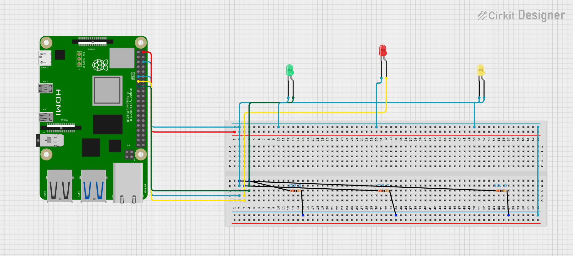
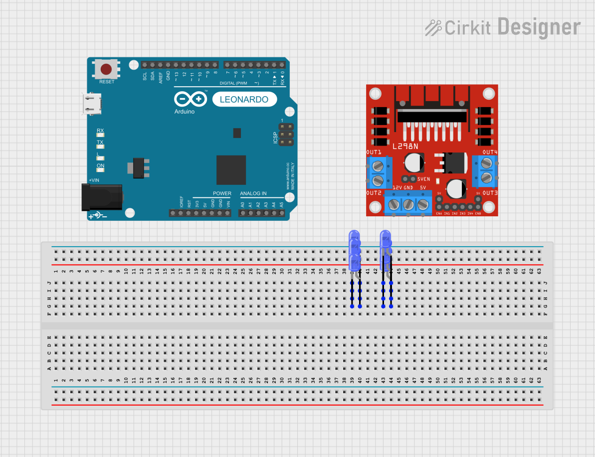
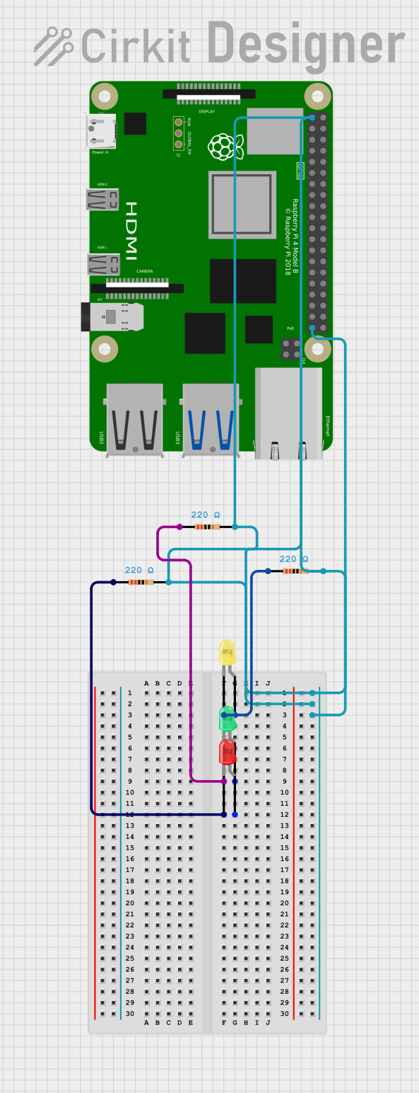
Explore Projects Built with RGB LED: Four Pin (Common Cathode)
Common Applications and Use Cases
- Mood lighting and ambient light control
- Color displays for information panels or signage
- User interface elements for electronic devices
- Art installations and stage lighting
- Educational projects and DIY electronics
Technical Specifications
Key Technical Details
- Forward Voltage (Typical): Red: 2.0-2.2V, Green: 3.0-3.2V, Blue: 3.0-3.2V
- Forward Current (Max): 20mA per color
- Luminous Intensity: Varies by color and current
- Viewing Angle: Typically around 120 degrees
Pin Configuration and Descriptions
| Pin Number | Description |
|---|---|
| 1 | Anode for Red LED |
| 2 | Anode for Green LED |
| 3 | Anode for Blue LED |
| 4 | Common Cathode (GND) |
Usage Instructions
How to Use the Component in a Circuit
- Connect the common cathode pin (Pin 4) to the ground (GND) of your power supply or microcontroller.
- Connect each anode pin (Pins 1, 2, and 3) to a current-limiting resistor, and then to the respective output pins on your microcontroller.
- To turn on a specific color, provide a HIGH signal to the corresponding anode pin.
- To create mixed colors, adjust the signal intensity (using PWM - Pulse Width Modulation) to each anode pin.
Important Considerations and Best Practices
- Always use current-limiting resistors to prevent damage to the LEDs.
- The sum of currents through the individual LEDs should not exceed the maximum rating for the common cathode.
- Use PWM for dimming and color mixing to achieve the desired color output.
- Avoid static discharge and overvoltage, which can permanently damage the LEDs.
Example Code for Arduino UNO
// Define the RGB LED pins
const int RED_PIN = 9;    // Red LED anode connected to digital pin 9
const int GREEN_PIN = 10; // Green LED anode connected to digital pin 10
const int BLUE_PIN = 11;  // Blue LED anode connected to digital pin 11

void setup() {
  // Set the LED pins as outputs
  pinMode(RED_PIN, OUTPUT);
  pinMode(GREEN_PIN, OUTPUT);
  pinMode(BLUE_PIN, OUTPUT);
}

void loop() {
  // Set the color to purple (Red + Blue)
  analogWrite(RED_PIN, 255);   // Full intensity for Red
  analogWrite(GREEN_PIN, 0);   // No Green
  analogWrite(BLUE_PIN, 255);  // Full intensity for Blue

  // Keep the color for 2 seconds
  delay(2000);

  // Turn off the LED
  analogWrite(RED_PIN, 0);
  analogWrite(GREEN_PIN, 0);
  analogWrite(BLUE_PIN, 0);

  // Wait for 1 second
  delay(1000);
}
Troubleshooting and FAQs
Common Issues Users Might Face
- LED not lighting up: Check connections and ensure the common cathode is connected to GND. Verify that the current-limiting resistors are correctly sized and properly connected.
- Dim or uneven color output: Ensure that each LED receives the appropriate forward voltage and current. Adjust PWM values for balanced color mixing.
- LED burned out: This can occur due to excessive current. Always use current-limiting resistors and do not exceed the maximum forward current.
Solutions and Tips for Troubleshooting
- Double-check wiring against the pin configuration table.
- Use a multimeter to verify the voltage across each LED and the current through each resistor.
- If using PWM, ensure that the microcontroller's pins support PWM and that the code is correctly implemented.
FAQs
Q: Can I power the RGB LED directly from an Arduino pin? A: Yes, but you must use current-limiting resistors to protect the LEDs and the Arduino pins.
Q: How do I calculate the value of the current-limiting resistors? A: Use Ohm's Law: R = (V_supply - V_forward) / I_forward, where V_supply is the supply voltage, V_forward is the forward voltage of the LED, and I_forward is the desired forward current.
Q: What is PWM and how does it control the LED colors? A: PWM stands for Pulse Width Modulation. It controls the brightness of each LED by rapidly turning it on and off at a frequency high enough that the human eye perceives it as a continuous light with varying intensity.