How to Use Mosfet module Correct: Examples, Pinouts, and Specs
Introduction
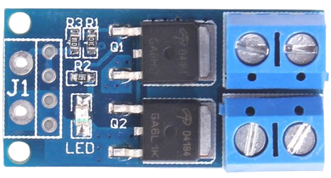
A MOSFET (Metal-Oxide-Semiconductor Field-Effect Transistor) module is a semiconductor device designed for switching or amplifying electronic signals. It is widely used in power electronics due to its ability to handle high voltage and current efficiently while minimizing power loss. MOSFET modules are essential in applications such as motor control, power supplies, inverters, and LED drivers.
Explore Projects Built with Mosfet module Correct
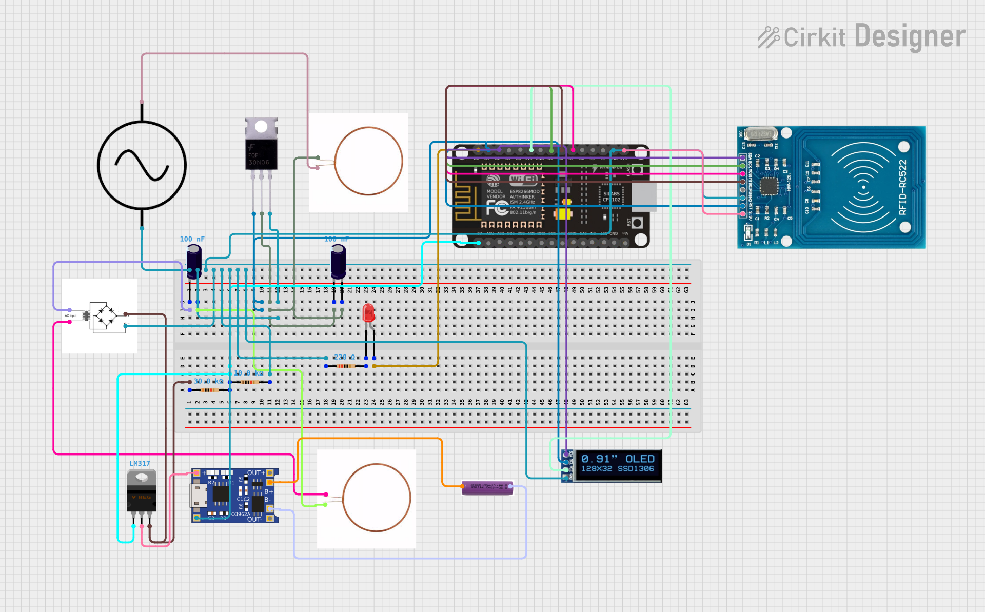
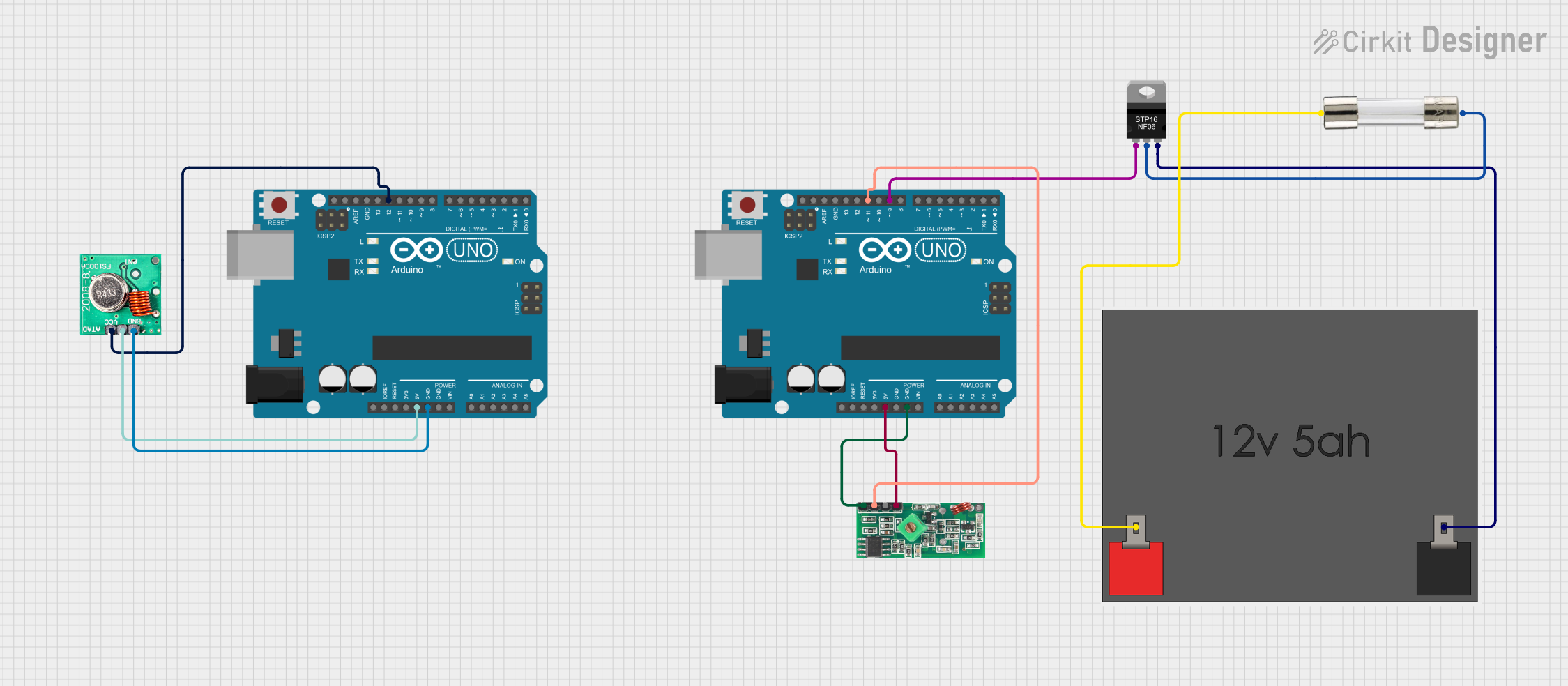


Explore Projects Built with Mosfet module Correct
Common Applications:
- Motor speed control in industrial and consumer devices
- DC-DC converters and power inverters
- LED dimming and lighting control
- Battery management systems
- High-frequency switching in power supplies
Technical Specifications
Below are the general technical specifications for a typical MOSFET module. Always refer to the specific datasheet for the exact part number.
Key Specifications:
- Voltage Rating (VDS): Up to 1000V (varies by model)
- Current Rating (ID): Up to 100A or more
- Gate Threshold Voltage (VGS(th)): 2V to 4V
- RDS(on) (On-Resistance): As low as 0.001Ω
- Switching Frequency: Up to 1MHz
- Package Type: TO-220, TO-247, or module-specific packages
- Operating Temperature Range: -55°C to +150°C
Pin Configuration and Descriptions
The pin configuration of a MOSFET module typically depends on the package type. Below is an example for a 3-pin TO-220 package:
| Pin Number | Pin Name | Description |
|---|---|---|
| 1 | Gate (G) | Controls the MOSFET switching state. |
| 2 | Drain (D) | Connects to the load or power source. |
| 3 | Source (S) | Connects to ground or return path. |
For modules with additional pins (e.g., 4-pin or 5-pin configurations), consult the specific datasheet for details.
Usage Instructions
How to Use the MOSFET Module in a Circuit
Gate Drive Circuit:
- Use a gate driver or a microcontroller to control the Gate (G) pin.
- Ensure the gate voltage (VGS) is within the specified range (e.g., 10V for full enhancement in most N-channel MOSFETs).
Load Connection:
- Connect the load between the Drain (D) and the positive power supply for an N-channel MOSFET.
- For a P-channel MOSFET, connect the load between the Source (S) and the positive power supply.
Power Supply:
- Ensure the power supply voltage does not exceed the MOSFET's maximum VDS rating.
Heat Dissipation:
- Attach a heatsink or use active cooling if the MOSFET operates at high currents to prevent overheating.
Example Circuit with Arduino UNO
Below is an example of using an N-channel MOSFET module to control an LED with an Arduino UNO:
// Define the MOSFET gate pin connected to Arduino
const int mosfetGatePin = 9; // Pin 9 is used for PWM output

void setup() {
  pinMode(mosfetGatePin, OUTPUT); // Set the MOSFET gate pin as output
}

void loop() {
  analogWrite(mosfetGatePin, 128); // Set PWM duty cycle to 50% (128/255)
  delay(1000); // Keep the LED ON for 1 second

  analogWrite(mosfetGatePin, 0); // Turn OFF the LED
  delay(1000); // Keep the LED OFF for 1 second
}
Important Considerations:
- Gate Resistor: Use a resistor (e.g., 10Ω) between the microcontroller and the Gate pin to limit inrush current.
- Flyback Diode: For inductive loads (e.g., motors), add a flyback diode across the load to protect the MOSFET from voltage spikes.
- Voltage Ratings: Ensure the MOSFET's voltage and current ratings exceed the requirements of your application.
Troubleshooting and FAQs
Common Issues and Solutions:
MOSFET Overheating:
- Cause: Insufficient cooling or excessive current.
- Solution: Use a heatsink or active cooling, and ensure the current is within the MOSFET's rating.
MOSFET Not Switching:
- Cause: Insufficient gate voltage or incorrect wiring.
- Solution: Verify the gate voltage (VGS) is within the specified range and check the circuit connections.
High Power Loss:
- Cause: High RDS(on) or improper gate drive.
- Solution: Use a MOSFET with lower RDS(on) and ensure the gate is fully enhanced (e.g., 10V for N-channel MOSFETs).
Microcontroller Damage:
- Cause: Voltage spikes or back EMF from the load.
- Solution: Add a flyback diode and use a gate resistor to protect the microcontroller.
FAQs:
Q: Can I use a MOSFET module with a 3.3V microcontroller?
A: Yes, but ensure the MOSFET's gate threshold voltage (VGS(th)) is low enough to fully turn on with 3.3V.Q: How do I choose between an N-channel and P-channel MOSFET?
A: N-channel MOSFETs are generally more efficient and are used for low-side switching, while P-channel MOSFETs are used for high-side switching.Q: Do I need a gate driver for my MOSFET module?
A: For high-power or high-speed applications, a gate driver is recommended to ensure fast and efficient switching.
This documentation provides a comprehensive guide to understanding and using a MOSFET module effectively. Always refer to the specific datasheet for your module for precise details.