How to Use Adafruit 1.2 Inch 8x8 LED Matrix Backpack Yellow: Examples, Pinouts, and Specs
Introduction
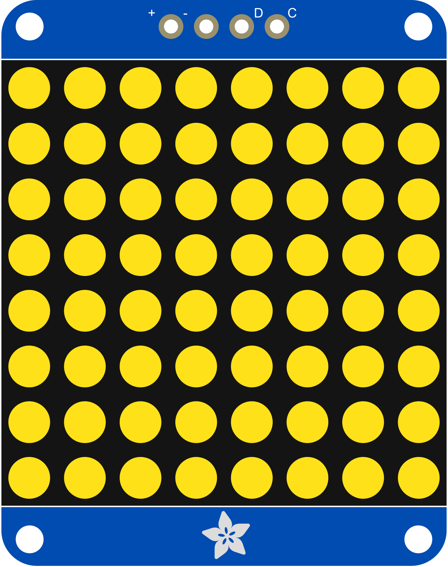
The Adafruit 1.2 Inch 8x8 LED Matrix Backpack Yellow is a compact and versatile electronic component that simplifies the process of driving an 8x8 LED matrix. This backpack integrates all the necessary circuitry to control each LED in the matrix and communicates via I2C, making it an ideal choice for projects where space is at a premium and ease of use is a priority. Common applications include creating digital signage, gaming displays, and adding visual output to various electronic projects.
Explore Projects Built with Adafruit 1.2 Inch 8x8 LED Matrix Backpack Yellow

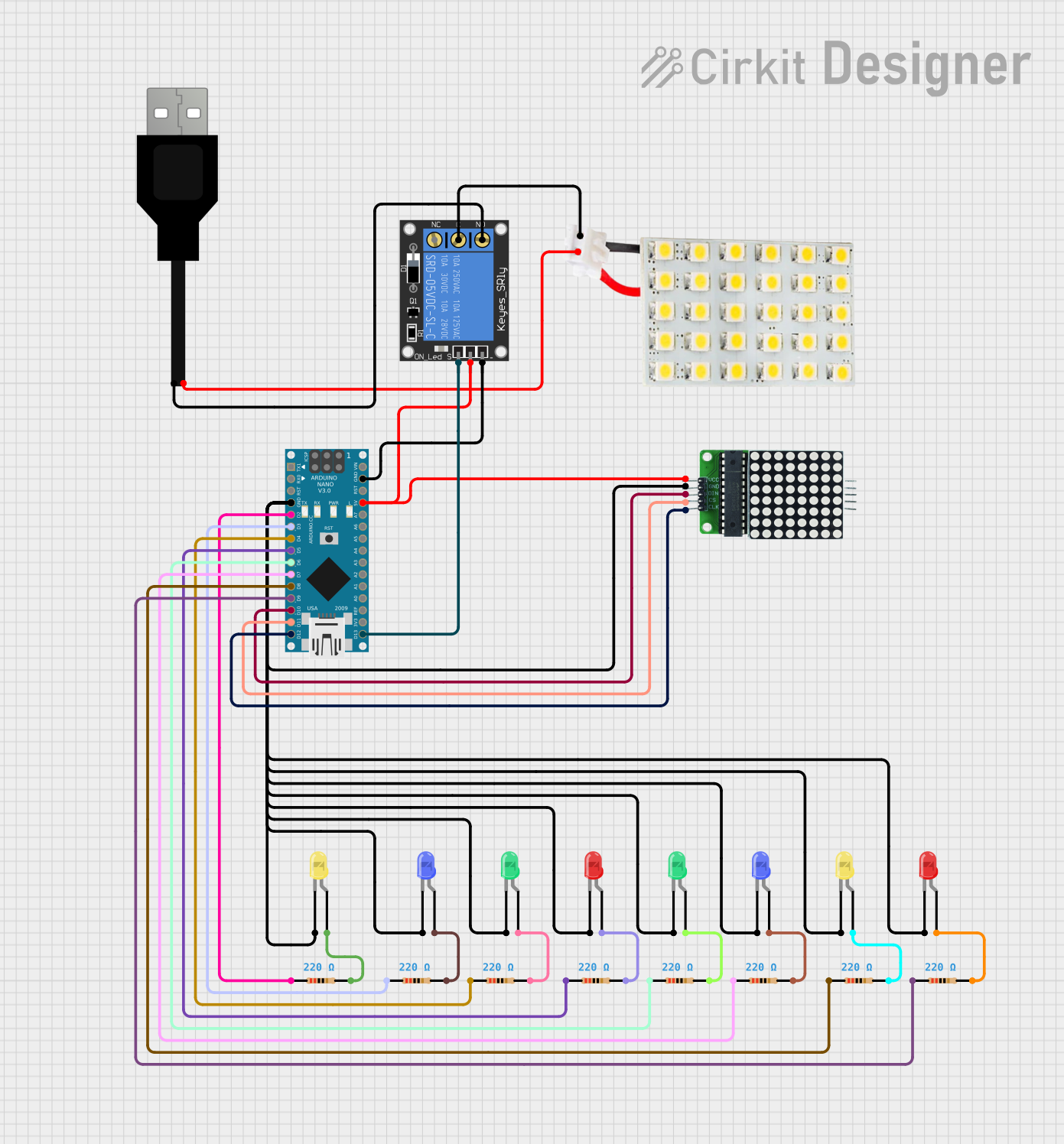
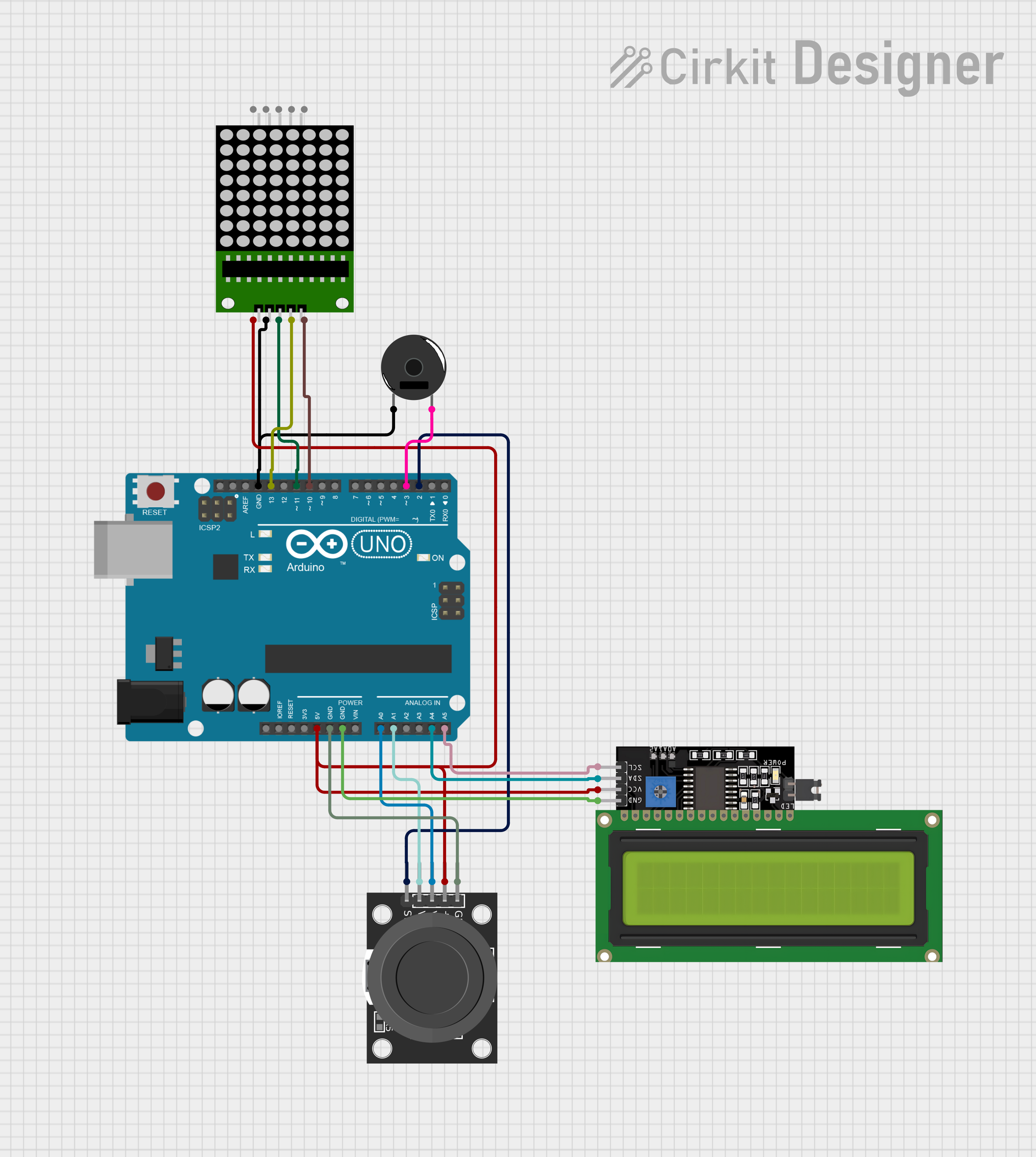

Explore Projects Built with Adafruit 1.2 Inch 8x8 LED Matrix Backpack Yellow
Technical Specifications
Key Technical Details
- Display Color: Yellow
- Matrix Size: 8x8 LEDs
- Operating Voltage: 4.5V - 5.5V
- Max Current (with all LEDs on): 320mA
- Communication: I2C interface
- I2C Addresses: 0x70 (default) - 0x77 (selectable with solder jumpers)
- Dimensions: 1.2" x 1.2" (30.5mm x 30.5mm)
Pin Configuration and Descriptions
| Pin Number | Name | Description |
|---|---|---|
| 1 | GND | Ground connection |
| 2 | VCC | Power supply (4.5V - 5.5V) |
| 3 | SDA | I2C Data line |
| 4 | SCL | I2C Clock line |
| 5 | ADDR | Address selection (connect to GND or VCC to change address) |
Usage Instructions
Integration with a Circuit
- Power Supply: Connect the VCC pin to a 4.5V - 5.5V power supply and the GND pin to the ground of your power source.
- I2C Communication: Connect the SDA and SCL pins to the corresponding I2C data and clock lines on your microcontroller (e.g., Arduino UNO).
- Address Selection: If using multiple LED matrix backpacks, change the I2C address by soldering the ADDR pin to either GND or VCC, according to the desired address.
Important Considerations and Best Practices
- Ensure that the power supply does not exceed 5.5V to prevent damage to the LED matrix.
- When all LEDs are on, the matrix can draw up to 320mA. Make sure your power supply can handle this current.
- Use pull-up resistors on the I2C lines if they are not already present on your microcontroller board.
- To avoid flickering, refresh the LED matrix display at a rate of at least 30Hz.
Example Code for Arduino UNO
#include <Wire.h>
#include <Adafruit_GFX.h>
#include <Adafruit_LEDBackpack.h>

Adafruit_8x8matrix matrix = Adafruit_8x8matrix();

void setup() {
  matrix.begin(0x70); // Initialize the matrix with the I2C address
  Wire.begin();       // Join the I2C bus as master
}

void loop() {
  matrix.clear();      // Clear the matrix display
  matrix.drawPixel(0, 0, LED_ON); // Turn on a single LED at (0,0)
  matrix.writeDisplay(); // Write the changes to the display
  delay(500);           // Wait for half a second
  matrix.clear();       // Clear the display again
  matrix.writeDisplay(); // Write the changes to the display
  delay(500);           // Wait for half a second
}
Troubleshooting and FAQs
Common Issues
- LEDs Not Lighting Up: Ensure that the power supply is correctly connected and within the specified voltage range. Check the I2C connections and verify that the correct I2C address is being used in your code.
- Flickering Display: Make sure the display is being refreshed at an adequate rate. A refresh rate that is too low can cause flickering.
- Dim LEDs: If the LEDs are dim, the power supply may be insufficient, or the current limit on your microcontroller's pins may be exceeded.
Solutions and Tips
- Double-check all connections and solder joints for reliability.
- Use a separate power supply if the current draw is too high for your microcontroller's power output.
- If using multiple LED matrix backpacks, ensure that each one has a unique I2C address.
FAQs
Q: Can I use this LED matrix with a 3.3V system? A: While the matrix is designed for 4.5V - 5.5V, it may work at 3.3V with reduced brightness. However, proper functionality is not guaranteed at this voltage.
Q: How do I change the I2C address? A: The I2C address can be changed by soldering the ADDR pin to either GND or VCC. Refer to the datasheet for the address mapping table.
Q: Can I control individual LEDs?
A: Yes, individual LEDs can be controlled using the drawPixel function in the provided library.
For further assistance, consult the Adafruit support forums or the product datasheet.