How to Use voltmeter pilot lamp: Examples, Pinouts, and Specs
Introduction
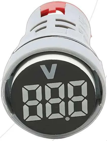
A voltmeter pilot lamp is an electronic component that combines the functionality of a voltage measurement device with a visual indicator, typically an LED or a small lamp. It is designed to provide a quick and easy way to monitor the voltage level within an electrical circuit and to indicate the presence of voltage with its built-in light. Common applications include monitoring battery levels, power supply units, and providing visual feedback on the operational status of electronic systems.
Explore Projects Built with voltmeter pilot lamp
Explore Projects Built with voltmeter pilot lamp
Technical Specifications
Key Technical Details
- Voltage Range: Typically 3V to 30V DC (may vary by model)
- Current Consumption: Depends on the built-in lamp, usually in the range of 10mA to 20mA
- Power Ratings: Power consumption is typically less than 1W
- Display Type: LED or incandescent lamp
- Accuracy: Varies by model, often within ±1% of the measured voltage
- Operating Temperature: -10°C to +65°C (may vary by model)
Pin Configuration and Descriptions
| Pin Number | Description | Notes |
|---|---|---|
| 1 | Positive Voltage In | Connect to the positive voltage |
| 2 | Negative Voltage In | Connect to the ground |
Usage Instructions
How to Use the Component in a Circuit
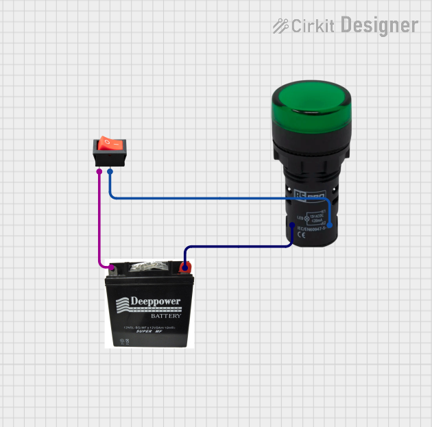
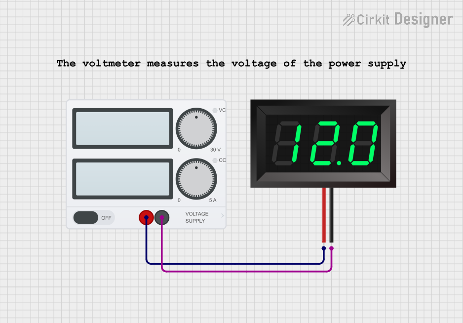
- Power Connections: Connect the positive voltage input pin to the point in the circuit where you want to measure the voltage. Connect the negative voltage input pin to the common ground of the circuit.
- Mounting: Secure the voltmeter pilot lamp in a location where it can be easily seen for visual monitoring.
- Testing: Once connected, power up the circuit and observe the pilot lamp. The lamp should light up if the voltage is within the specified range of the voltmeter.
Important Considerations and Best Practices
- Voltage Limits: Do not exceed the maximum voltage rating of the voltmeter pilot lamp to avoid damage.
- Polarity: Ensure correct polarity when connecting the voltmeter pilot lamp to prevent damage to the component or inaccurate readings.
- Isolation: If the circuit involves high voltages, take appropriate precautions to isolate the voltmeter pilot lamp from the high voltage sections to ensure safety.
Troubleshooting and FAQs
Common Issues
- Lamp Does Not Illuminate: Check the connections for proper polarity and ensure that the voltage is within the range of the voltmeter pilot lamp.
- Inaccurate Readings: Verify that the component is not damaged and that there is no significant voltage drop across the connections.
Solutions and Tips for Troubleshooting
- Connection Check: Double-check all connections for any loose wires or poor contacts.
- Voltage Range: Ensure the voltage in the circuit is within the operating range of the voltmeter pilot lamp.
- Component Testing: Test the voltmeter pilot lamp in a known working circuit to determine if the component is functioning correctly.
FAQs
Q: Can the voltmeter pilot lamp be used with AC voltage? A: Typically, voltmeter pilot lamps are designed for DC voltage applications. Check the manufacturer's specifications for AC compatibility.
Q: Is calibration required for the voltmeter pilot lamp? A: Most voltmeter pilot lamps are pre-calibrated and do not require user calibration. However, for precise applications, refer to the manufacturer's instructions for calibration procedures.
Q: How do I know if the voltmeter pilot lamp is suitable for my application? A: Compare your application's voltage range and environmental conditions with the technical specifications of the voltmeter pilot lamp to ensure compatibility.
Example Arduino UNO Code
// This example demonstrates how to use a voltmeter pilot lamp with an Arduino UNO.

int voltmeterPin = A0; // Analog input pin connected to the voltmeter pilot lamp
int lampPin = 13;      // Digital pin connected to the built-in lamp (LED)

void setup() {
  pinMode(lampPin, OUTPUT); // Set the lamp pin as an output
  Serial.begin(9600);       // Start serial communication at 9600 baud
}

void loop() {
  int sensorValue = analogRead(voltmeterPin); // Read the voltage
  float voltage = sensorValue * (5.0 / 1023.0); // Convert to voltage
  Serial.println(voltage); // Print the voltage to the Serial Monitor

  // If the voltage is above a certain threshold, turn on the lamp
  if (voltage > 2.5) { // Threshold voltage
    digitalWrite(lampPin, HIGH); // Turn on the lamp
  } else {
    digitalWrite(lampPin, LOW); // Turn off the lamp
  }

  delay(1000); // Wait for a second before reading again
}
Note: The above code is a simple demonstration and may need to be adjusted based on the specific voltmeter pilot lamp used and the voltage range of interest. The threshold voltage in the if statement should be set according to the desired indication level.