How to Use START PUSH BUTTON: Examples, Pinouts, and Specs
Introduction
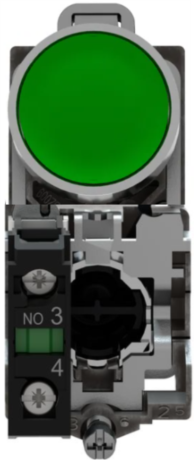
The START PUSH BUTTON (Manufacturer: Schneider, Part ID: XB4-BA31) is a momentary switch designed to complete an electrical circuit when pressed. It is commonly used to initiate a function or process in electronic devices, industrial control systems, and automation applications. This robust and reliable component is ideal for environments requiring frequent operation and high durability.
Explore Projects Built with START PUSH BUTTON

Explore Projects Built with START PUSH BUTTON
Common Applications and Use Cases
- Industrial machinery start/stop controls
- Automation systems
- Consumer electronics
- Robotics and mechatronics
- Emergency stop/start systems
Technical Specifications
The following table outlines the key technical details of the Schneider XB4-BA31 START PUSH BUTTON:
| Parameter | Specification |
|---|---|
| Manufacturer | Schneider |
| Part ID | XB4-BA31 |
| Switch Type | Momentary |
| Contact Configuration | 1 Normally Open (NO) |
| Operating Voltage | 24V to 240V AC/DC |
| Rated Current | 10A |
| Mechanical Durability | 1,000,000 cycles |
| Mounting Type | Panel mount |
| Button Material | Plastic (high durability) |
| Operating Temperature | -25°C to +70°C |
| IP Rating | IP66 (dust-tight and water-resistant) |
Pin Configuration and Descriptions
The START PUSH BUTTON has a simple pin configuration, as shown below:
| Pin Name | Description |
|---|---|
| NO | Normally Open contact; closes when pressed. |
| COM | Common terminal for the circuit connection. |
Usage Instructions
How to Use the Component in a Circuit
- Mounting the Button: Secure the START PUSH BUTTON into a panel or enclosure using the provided mounting hardware. Ensure the button is firmly fixed to prevent movement during operation.
- Wiring:
- Connect the COM terminal to the power source or ground, depending on your circuit design.
- Connect the NO terminal to the load or control circuit.
- Operation: When the button is pressed, the NO contact closes, completing the circuit and allowing current to flow. Releasing the button opens the circuit.
Important Considerations and Best Practices
- Voltage and Current Ratings: Ensure the operating voltage and current do not exceed the specified limits (240V AC/DC, 10A).
- Debouncing: For digital circuits, implement a debouncing mechanism (hardware or software) to avoid false triggering due to mechanical bounce.
- Environmental Protection: The IP66 rating ensures protection against dust and water. However, avoid submerging the button in water or exposing it to extreme conditions beyond its rated temperature range.
- Safety: Always disconnect power before wiring or servicing the button to prevent electrical shock.
Example: Connecting to an Arduino UNO
The START PUSH BUTTON can be easily interfaced with an Arduino UNO for digital input. Below is an example circuit and code:
Circuit Diagram
- Connect the COM terminal to the Arduino's GND pin.
- Connect the NO terminal to a digital input pin (e.g., pin 2) on the Arduino.
- Use a pull-down resistor (10kΩ) between the NO terminal and GND to ensure a stable LOW state when the button is not pressed.
Arduino Code
// Define the pin connected to the START PUSH BUTTON
const int buttonPin = 2;  // Digital pin 2 for button input
const int ledPin = 13;    // Built-in LED for output

void setup() {
  pinMode(buttonPin, INPUT);  // Set button pin as input
  pinMode(ledPin, OUTPUT);   // Set LED pin as output
  digitalWrite(ledPin, LOW); // Ensure LED is off initially
}

void loop() {
  int buttonState = digitalRead(buttonPin); // Read button state

  if (buttonState == HIGH) {
    // If button is pressed, turn on the LED
    digitalWrite(ledPin, HIGH);
  } else {
    // If button is not pressed, turn off the LED
    digitalWrite(ledPin, LOW);
  }
}
Troubleshooting and FAQs
Common Issues and Solutions
Button Not Responding:
- Cause: Loose or incorrect wiring.
- Solution: Verify all connections, ensuring the COM and NO terminals are properly wired.
False Triggering:
- Cause: Mechanical bounce or noise in the circuit.
- Solution: Add a pull-down resistor and/or implement software debouncing in your code.
Button Sticking:
- Cause: Dirt or debris in the button mechanism.
- Solution: Clean the button with compressed air or a soft brush. Avoid using harsh chemicals.
Overheating:
- Cause: Exceeding the rated current or voltage.
- Solution: Ensure the circuit operates within the specified limits (10A, 240V AC/DC).
FAQs
Q1: Can the START PUSH BUTTON be used outdoors?
A1: Yes, the IP66 rating ensures it is dust-tight and water-resistant, making it suitable for outdoor use. However, avoid prolonged exposure to extreme weather conditions.
Q2: Can I use this button with a 5V microcontroller?
A2: Yes, the button can be used with 5V systems. Ensure proper wiring and use a pull-down resistor for stable operation.
Q3: What is the lifespan of the button?
A3: The mechanical durability is rated at 1,000,000 cycles, ensuring long-term reliability.
Q4: Is the button available in different colors?
A4: Yes, Schneider offers the XB4 series in various colors for different applications. Check the manufacturer's catalog for options.