How to Use RPM sensor: Examples, Pinouts, and Specs
Introduction
An RPM sensor is a device used to measure the rotational speed of a shaft or disk, typically expressed in revolutions per minute (RPM). It plays a critical role in monitoring and controlling the performance of rotating machinery. RPM sensors are widely used in automotive applications to monitor engine speed, as well as in industrial settings to ensure the proper operation of motors, turbines, and other rotating equipment.
Explore Projects Built with RPM sensor
Explore Projects Built with RPM sensor
Common Applications and Use Cases
- Automotive: Monitoring engine RPM for fuel efficiency and performance optimization.
- Industrial: Measuring the speed of motors, turbines, and conveyor belts.
- Robotics: Ensuring precise control of motor-driven systems.
- HVAC Systems: Monitoring fan and blower speeds.
- Wind Turbines: Measuring rotor speed for performance analysis.
Technical Specifications
Below are the general technical specifications for a typical RPM sensor. Note that specific values may vary depending on the model and manufacturer.
Key Technical Details
- Operating Voltage: 5V to 24V DC (varies by model)
- Output Signal: Digital (Pulse) or Analog (Voltage/Current)
- Sensing Range: 0 to 10,000 RPM (typical)
- Accuracy: ±1% of full scale
- Operating Temperature: -40°C to 85°C
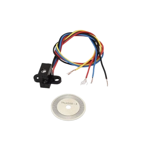
- Sensor Type: Hall-effect, Optical, or Magnetic
Pin Configuration and Descriptions
The pin configuration of an RPM sensor depends on its type. Below is an example for a 3-pin Hall-effect RPM sensor:
| Pin | Name | Description |
|---|---|---|
| 1 | VCC | Power supply input (typically 5V or 12V DC). |
| 2 | GND | Ground connection. |
| 3 | Signal Output | Outputs a digital pulse signal corresponding to the rotational speed of the shaft. |
For a 4-pin optical RPM sensor, the configuration may look like this:
| Pin | Name | Description |
|---|---|---|
| 1 | VCC | Power supply input (typically 5V DC). |
| 2 | GND | Ground connection. |
| 3 | Signal Output | Outputs a digital pulse signal corresponding to the RPM. |
| 4 | Enable | Optional pin to enable or disable the sensor (active high). |
Usage Instructions
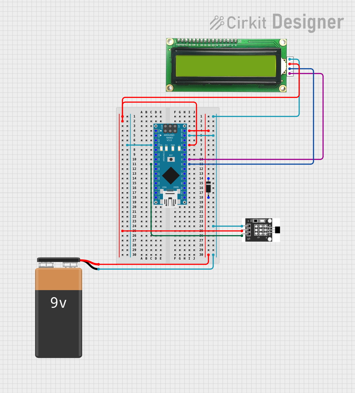
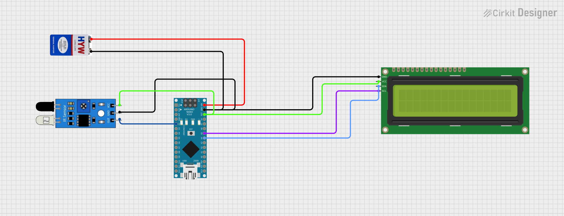
How to Use the RPM Sensor in a Circuit
- Power the Sensor: Connect the VCC pin to a suitable power source (e.g., 5V or 12V DC) and the GND pin to the ground of your circuit.
- Connect the Signal Output: Connect the signal output pin to a microcontroller or frequency counter to measure the pulse signal.
- Read the Signal: The sensor outputs a series of pulses, where the frequency of the pulses corresponds to the rotational speed of the shaft. Use a microcontroller to count the pulses and calculate the RPM.
Important Considerations and Best Practices
- Power Supply: Ensure the sensor is powered with the correct voltage to avoid damage.
- Signal Conditioning: Use a pull-up resistor on the signal output pin if required by the sensor.
- Placement: Position the sensor close to the rotating object, ensuring proper alignment for accurate readings.
- Debouncing: Implement software debouncing to filter out noise in the signal.
- Calibration: Calibrate the sensor to account for variations in the number of pulses per revolution (PPR).
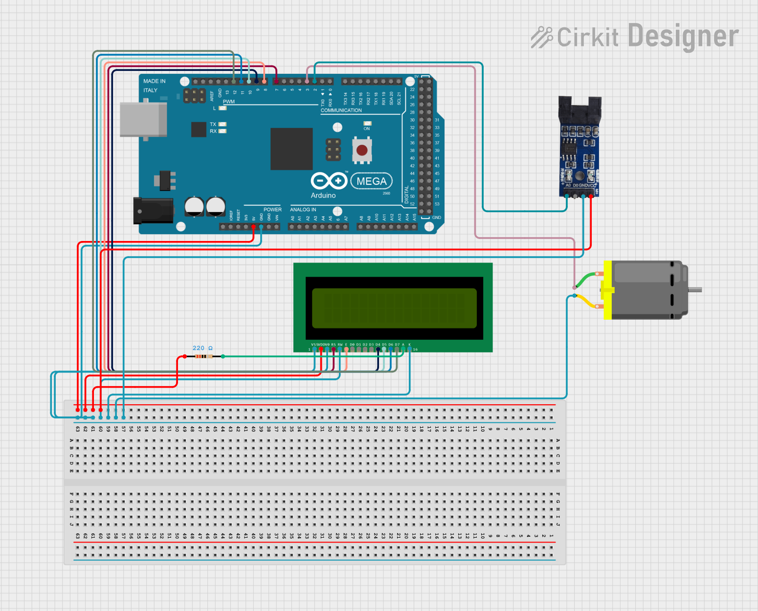
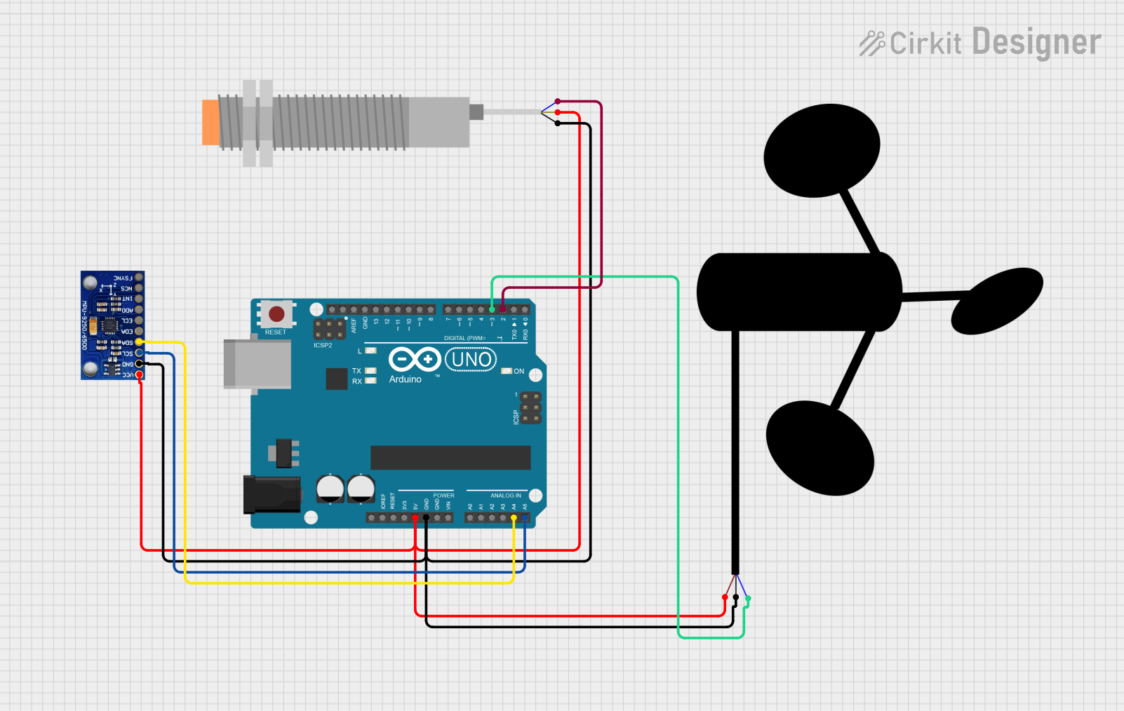
Example: Using an RPM Sensor with Arduino UNO
Below is an example of how to use a Hall-effect RPM sensor with an Arduino UNO to measure RPM:
// Define the pin connected to the RPM sensor's signal output
const int rpmSensorPin = 2;

// Variables to store pulse count and RPM
volatile unsigned int pulseCount = 0;
unsigned long lastTime = 0;
unsigned int rpm = 0;

// Interrupt service routine to count pulses
void countPulses() {
  pulseCount++;
}

void setup() {
  // Initialize serial communication for debugging
  Serial.begin(9600);

  // Set up the RPM sensor pin as an input
  pinMode(rpmSensorPin, INPUT_PULLUP);

  // Attach an interrupt to the RPM sensor pin (rising edge)
  attachInterrupt(digitalPinToInterrupt(rpmSensorPin), countPulses, RISING);
}

void loop() {
  // Calculate RPM every second
  unsigned long currentTime = millis();
  if (currentTime - lastTime >= 1000) {
    // Calculate RPM: (pulseCount / pulsesPerRevolution) * 60
    // Assuming 1 pulse per revolution for simplicity
    rpm = pulseCount * 60;

    // Reset pulse count and update last time
    pulseCount = 0;
    lastTime = currentTime;

    // Print RPM to the serial monitor
    Serial.print("RPM: ");
    Serial.println(rpm);
  }
}
Notes:
- Replace
pulsesPerRevolutionin the formula with the actual number of pulses per revolution for your sensor. - Ensure the sensor is properly aligned with the rotating object for accurate readings.
Troubleshooting and FAQs
Common Issues and Solutions
No Signal Output:
- Check the power supply voltage and connections.
- Ensure the sensor is properly aligned with the rotating object.
- Verify that the signal output pin is connected to the correct microcontroller pin.
Inaccurate RPM Readings:
- Calibrate the sensor to account for the correct number of pulses per revolution.
- Use software debouncing to filter out noise in the signal.
- Ensure the sensor is not too far from the rotating object.
Intermittent Signal:
- Check for loose or faulty connections.
- Verify that the rotating object has a consistent surface for the sensor to detect.
FAQs
Q: Can I use an RPM sensor with a 3.3V microcontroller?
A: Yes, but ensure the sensor's output signal is compatible with 3.3V logic levels. You may need a level shifter if the sensor operates at a higher voltage.
Q: How do I calculate RPM if my sensor outputs multiple pulses per revolution?
A: Divide the total pulse count by the number of pulses per revolution, then multiply by 60 to get RPM.
Q: Can an RPM sensor work in a high-temperature environment?
A: Most RPM sensors are rated for temperatures up to 85°C. For higher temperatures, use a sensor specifically designed for such conditions.
Q: What type of RPM sensor should I use for a non-metallic rotating object?
A: An optical RPM sensor is ideal for non-metallic objects, as it uses light reflection to detect rotation.