How to Use 0.96inch LCD module 160x80: Examples, Pinouts, and Specs
Introduction
The 0.96inch LCD Module 160x80 is a compact liquid crystal display (LCD) designed for use in embedded systems and electronics projects. With a resolution of 160x80 pixels, this module is ideal for displaying text, simple graphics, and basic user interfaces. Its small size and low power consumption make it a popular choice for portable devices, IoT applications, and hobbyist projects.
Explore Projects Built with 0.96inch LCD module 160x80

Explore Projects Built with 0.96inch LCD module 160x80
Common Applications
- Wearable devices
- IoT dashboards and displays
- Portable measurement tools
- Embedded system interfaces
- Educational and DIY electronics projects
Technical Specifications
Below are the key technical details of the 0.96inch LCD Module 160x80:
| Parameter | Value |
|---|---|
| Display Type | TFT LCD |
| Resolution | 160x80 pixels |
| Display Size | 0.96 inches (diagonal) |
| Interface | SPI (Serial Peripheral Interface) |
| Operating Voltage | 3.3V (logic level) |
| Power Consumption | Low power |
| Backlight | LED |
| Viewing Angle | Wide |
| Driver IC | ST7735 or compatible |
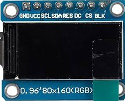
Pin Configuration
The module typically has the following pinout:
| Pin | Name | Description |
|---|---|---|
| 1 | GND | Ground connection |
| 2 | VCC | Power supply (3.3V) |
| 3 | SCL | Serial Clock Line (SPI clock input) |
| 4 | SDA | Serial Data Line (SPI data input) |
| 5 | RES | Reset pin (active low) |
| 6 | DC | Data/Command control pin |
| 7 | CS | Chip Select (active low) |
| 8 | BLK | Backlight control (connect to VCC for always-on) |
Usage Instructions
Connecting the Module
To use the 0.96inch LCD Module 160x80 in a circuit, follow these steps:
- Connect the GND pin of the module to the ground of your microcontroller.
- Connect the VCC pin to a 3.3V power supply.
- Connect the SCL pin to the SPI clock pin of your microcontroller.
- Connect the SDA pin to the SPI data pin of your microcontroller.
- Connect the RES pin to a GPIO pin for resetting the display.
- Connect the DC pin to a GPIO pin to toggle between data and command modes.
- Connect the CS pin to a GPIO pin to enable or disable the module.
- Optionally, connect the BLK pin to control the backlight (or tie it to VCC for always-on).
Important Considerations
- Ensure the module operates at 3.3V logic levels. If your microcontroller uses 5V logic, use a level shifter to avoid damaging the module.
- Use appropriate pull-up resistors if required by your SPI configuration.
- Avoid excessive current draw by limiting the backlight brightness if adjustable.
Example Code for Arduino UNO
Below is an example of how to use the 0.96inch LCD Module 160x80 with an Arduino UNO. This example uses the Adafruit GFX and Adafruit ST7735 libraries.
#include <Adafruit_GFX.h>    // Core graphics library
#include <Adafruit_ST7735.h> // Library for ST7735 driver
#include <SPI.h>             // SPI library

// Define pin connections
#define TFT_CS     10  // Chip Select pin
#define TFT_RST    9   // Reset pin
#define TFT_DC     8   // Data/Command pin

// Initialize the display object
Adafruit_ST7735 tft = Adafruit_ST7735(TFT_CS, TFT_DC, TFT_RST);

void setup() {
  // Initialize the serial monitor
  Serial.begin(9600);
  Serial.println("Initializing display...");

  // Initialize the display
  tft.initR(INITR_BLACKTAB); // Use the appropriate initialization for your module
  tft.setRotation(1);        // Set display orientation (0-3)
  tft.fillScreen(ST77XX_BLACK); // Clear the screen with black color

  // Display a message
  tft.setTextColor(ST77XX_WHITE); // Set text color to white
  tft.setTextSize(1);             // Set text size
  tft.setCursor(0, 0);            // Set cursor position
  tft.println("Hello, World!");   // Print text to the display
}

void loop() {
  // Add your code here to update the display
}
Notes:
- Install the Adafruit GFX and Adafruit ST7735 libraries via the Arduino Library Manager before running the code.
- Adjust the
tft.initR()parameter if your module uses a different initialization sequence.
Troubleshooting and FAQs
Common Issues
The display does not turn on.
- Verify all connections, especially power (VCC and GND).
- Ensure the backlight pin (BLK) is connected to VCC or properly controlled.
The display shows a blank screen.
- Check the SPI connections (SCL, SDA, CS, DC, RES).
- Ensure the correct initialization sequence is used in the code.
The text or graphics appear distorted.
- Verify the display orientation using
tft.setRotation(). - Ensure the resolution and driver settings match the module specifications.
- Verify the display orientation using
The display flickers or resets intermittently.
- Check for loose connections or insufficient power supply.
- Use decoupling capacitors near the power pins to stabilize the voltage.
Tips for Troubleshooting
- Use a multimeter to check for continuity and proper voltage levels.
- Test the module with a simple example code to isolate hardware issues.
- Refer to the datasheet of the driver IC (ST7735) for advanced debugging.
By following this documentation, you should be able to successfully integrate and use the 0.96inch LCD Module 160x80 in your projects.