Cirkit Designer Logo
Cirkit Designer
Your all-in-one circuit design IDE
Home / 
Component Documentation

How to Use pca9685: Examples, Pinouts, and Specs

Image of pca9685
Cirkit Designer LogoDesign with pca9685 in Cirkit Designer

Introduction

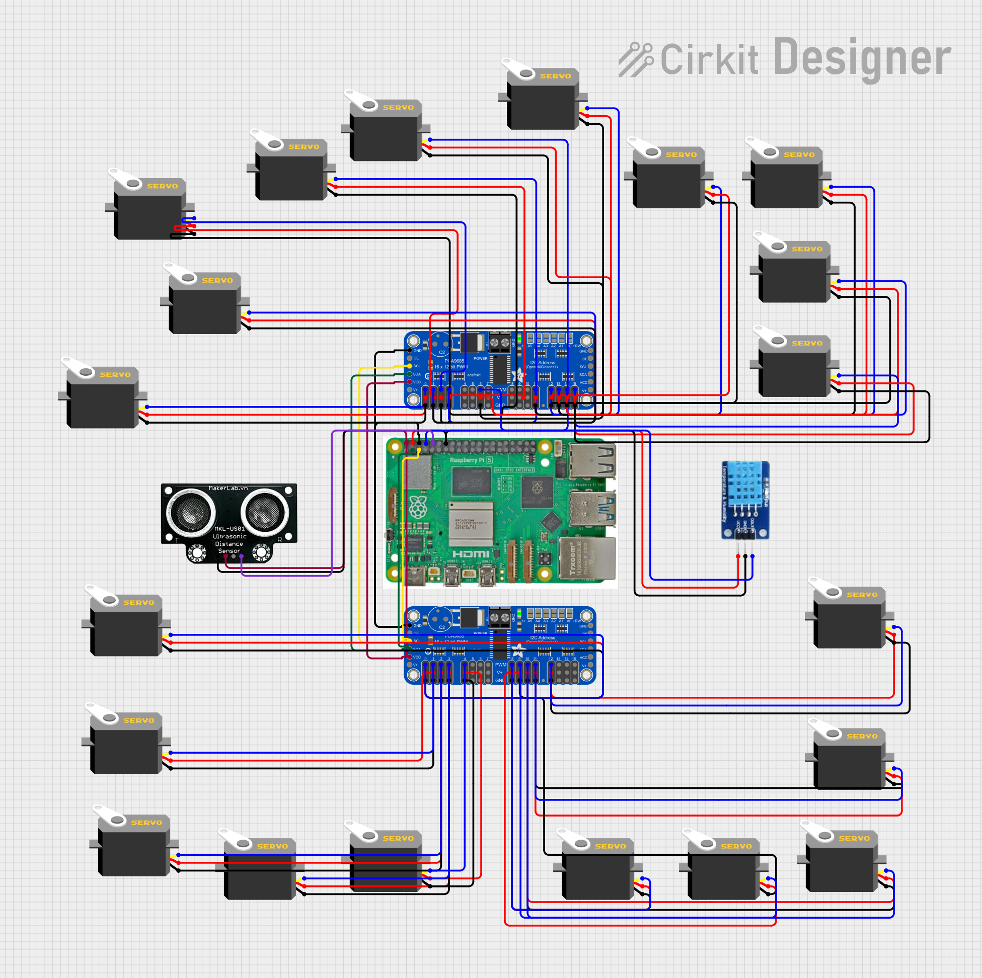
The PCA9685 is a 16-channel, 12-bit PWM (Pulse Width Modulation) controller that communicates via the I2C protocol. It is widely used in robotics, automation, and lighting projects due to its ability to control up to 16 independent PWM outputs with high precision. This component is particularly useful for driving servos, LEDs, and other devices requiring PWM signals, while offloading the processing burden from the microcontroller.

Explore Projects Built with pca9685

Use Cirkit Designer to design, explore, and prototype these projects online. Some projects support real-time simulation. Click "Open Project" to start designing instantly!
Raspberry Pi-Controlled Dual Servo Driver with PCA9685 Interface
Image of Copy of PWM, SERVO, ESC Wiring: A project utilizing pca9685 in a practical application
This circuit controls two servomotors (MG996R and MG995) using a Raspberry Pi 5 and an Adafruit PCA9685 PWM Servo Breakout board. The Raspberry Pi communicates with the PCA9685 via I2C (using GPIO 2 and GPIO 3 for SDA and SCL, respectively) to send PWM signals to the servos. Power distribution is managed through an Adafruit Perma Proto Small Mint board, which connects the 5V and GND from the Raspberry Pi to the PCA9685 and the servos.
Cirkit Designer LogoOpen Project in Cirkit Designer
8-Channel Servo Controller with Arduino and PCA9685
Image of spiderbot: A project utilizing pca9685 in a practical application
This circuit is designed to control multiple servos using an Adafruit PCA9685 PWM Servo Breakout board, which is interfaced with an Arduino UNO microcontroller. The PCA9685 board receives power from a 9V battery and communicates with the Arduino via I2C (SDA/SCL lines). The Arduino is programmed to generate PWM signals through the PCA9685 to independently control the position of each connected servo.
Cirkit Designer LogoOpen Project in Cirkit Designer
Arduino UNO and PCA9685 Controlled Robotic Arm with Bluetooth and Audio Feedback
Image of spiderbot: A project utilizing pca9685 in a practical application
This circuit is a multi-functional robotic control system powered by an Arduino UNO, which interfaces with a PCA9685 PWM driver to control multiple servos, an L298N motor driver to control two DC motors, and a DFPlayer Mini for audio playback. The system is designed to be controlled via Bluetooth using an HC-05 module, allowing for remote operation of servos, motors, and audio playback.
Cirkit Designer LogoOpen Project in Cirkit Designer
Raspberry Pi 5-Controlled Multi-Servo System with Environmental Sensing
Image of cit: A project utilizing pca9685 in a practical application
This circuit is designed to control multiple servos using two Adafruit PCA9685 PWM Servo Breakout boards, which are interfaced with a Raspberry Pi 5. The Raspberry Pi provides power and control signals to the PCA9685 boards, which in turn generate PWM signals to control the position of each servo. Additional sensors, including a DHT11 temperature and humidity sensor and an MKE-S01 ultrasonic distance sensor, are connected to the Raspberry Pi for environmental data acquisition.
Cirkit Designer LogoOpen Project in Cirkit Designer

Explore Projects Built with pca9685

Use Cirkit Designer to design, explore, and prototype these projects online. Some projects support real-time simulation. Click "Open Project" to start designing instantly!
Image of Copy of PWM, SERVO, ESC Wiring: A project utilizing pca9685 in a practical application
Raspberry Pi-Controlled Dual Servo Driver with PCA9685 Interface
This circuit controls two servomotors (MG996R and MG995) using a Raspberry Pi 5 and an Adafruit PCA9685 PWM Servo Breakout board. The Raspberry Pi communicates with the PCA9685 via I2C (using GPIO 2 and GPIO 3 for SDA and SCL, respectively) to send PWM signals to the servos. Power distribution is managed through an Adafruit Perma Proto Small Mint board, which connects the 5V and GND from the Raspberry Pi to the PCA9685 and the servos.
Cirkit Designer LogoOpen Project in Cirkit Designer
Image of spiderbot: A project utilizing pca9685 in a practical application
8-Channel Servo Controller with Arduino and PCA9685
This circuit is designed to control multiple servos using an Adafruit PCA9685 PWM Servo Breakout board, which is interfaced with an Arduino UNO microcontroller. The PCA9685 board receives power from a 9V battery and communicates with the Arduino via I2C (SDA/SCL lines). The Arduino is programmed to generate PWM signals through the PCA9685 to independently control the position of each connected servo.
Cirkit Designer LogoOpen Project in Cirkit Designer
Image of spiderbot: A project utilizing pca9685 in a practical application
Arduino UNO and PCA9685 Controlled Robotic Arm with Bluetooth and Audio Feedback
This circuit is a multi-functional robotic control system powered by an Arduino UNO, which interfaces with a PCA9685 PWM driver to control multiple servos, an L298N motor driver to control two DC motors, and a DFPlayer Mini for audio playback. The system is designed to be controlled via Bluetooth using an HC-05 module, allowing for remote operation of servos, motors, and audio playback.
Cirkit Designer LogoOpen Project in Cirkit Designer
Image of cit: A project utilizing pca9685 in a practical application
Raspberry Pi 5-Controlled Multi-Servo System with Environmental Sensing
This circuit is designed to control multiple servos using two Adafruit PCA9685 PWM Servo Breakout boards, which are interfaced with a Raspberry Pi 5. The Raspberry Pi provides power and control signals to the PCA9685 boards, which in turn generate PWM signals to control the position of each servo. Additional sensors, including a DHT11 temperature and humidity sensor and an MKE-S01 ultrasonic distance sensor, are connected to the Raspberry Pi for environmental data acquisition.
Cirkit Designer LogoOpen Project in Cirkit Designer

Common Applications

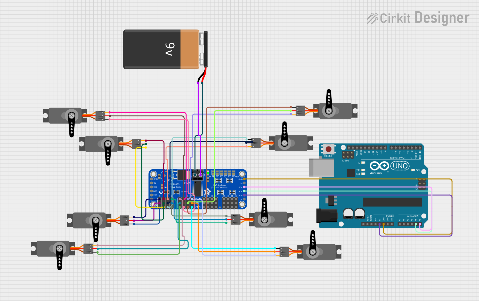
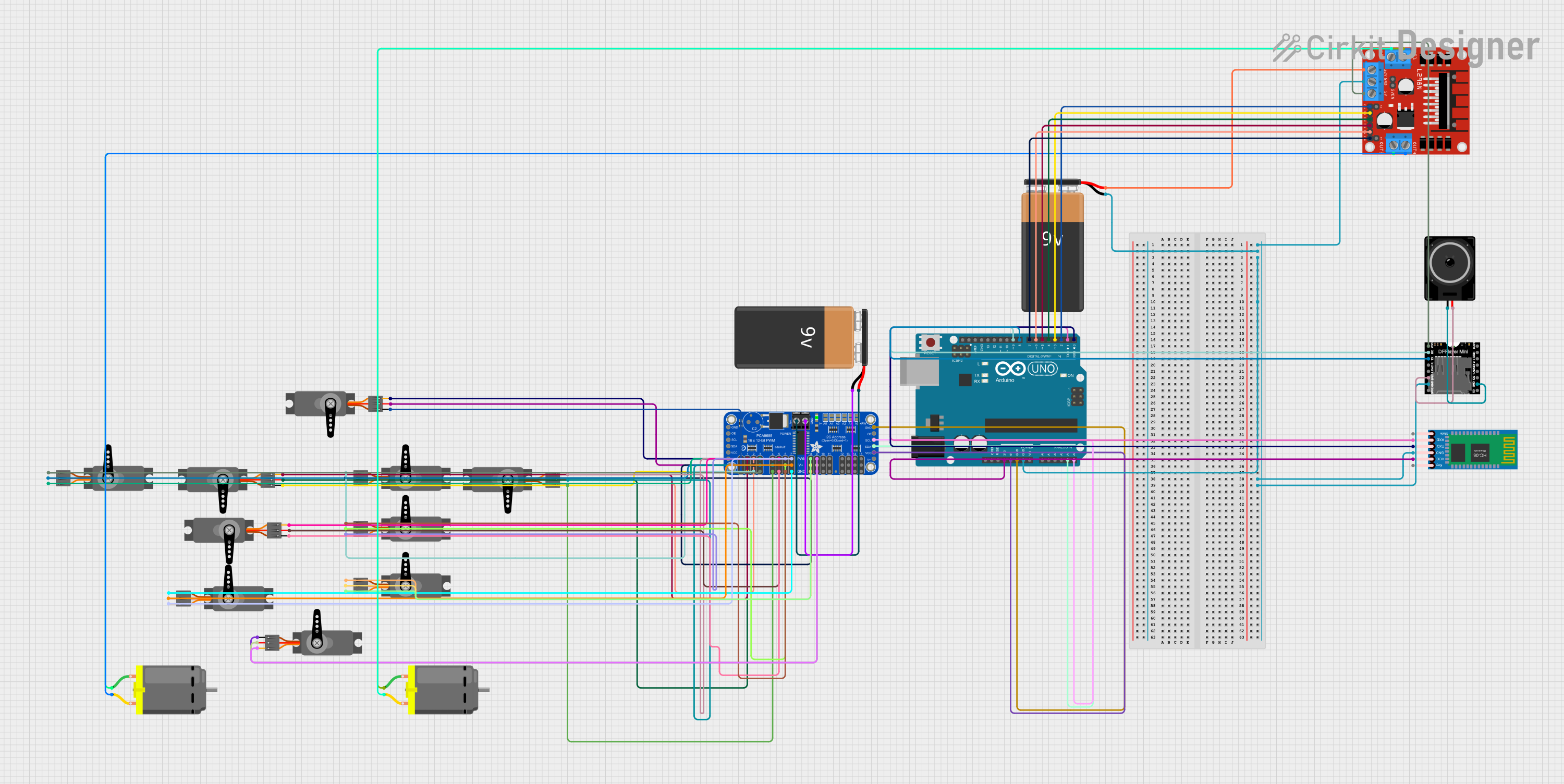
  • Controlling servo motors in robotic arms, drones, and RC vehicles
  • LED dimming and RGB lighting control
  • Stepper motor control
  • General-purpose PWM signal generation for automation systems

Technical Specifications

Key Technical Details

  • Number of Channels: 16 independent PWM outputs
  • Resolution: 12-bit (4096 steps per channel)
  • Communication Protocol: I2C (up to 1 MHz)
  • Operating Voltage: 2.3V to 5.5V
  • Output Voltage: Matches supply voltage (VCC)
  • Output Current: Up to 25 mA per channel (sink), 10 mA (source)
  • PWM Frequency: Adjustable from 24 Hz to 1526 Hz
  • I2C Address Range: 0x40 to 0x7F (configurable via address pins)
  • Package: TSSOP-28 or SOIC-28

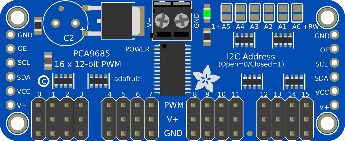
Pin Configuration and Descriptions

The PCA9685 has 28 pins. Below is a description of the key pins:

Pin Name Type Description
VCC Power Supply voltage (2.3V to 5.5V).
GND Ground Ground connection.
SDA Input/Output I2C data line.
SCL Input I2C clock line.
OE Input Output enable (active low). Disables all outputs when high.
A0–A5 Input Address pins for configuring the I2C address.
OUT0–OUT15 Output PWM output channels.
EXTCLK Input External clock input (optional).
V+ Power External power supply for driving servos or LEDs (separate from VCC).
RESET Input Resets the device when pulled low.

Usage Instructions

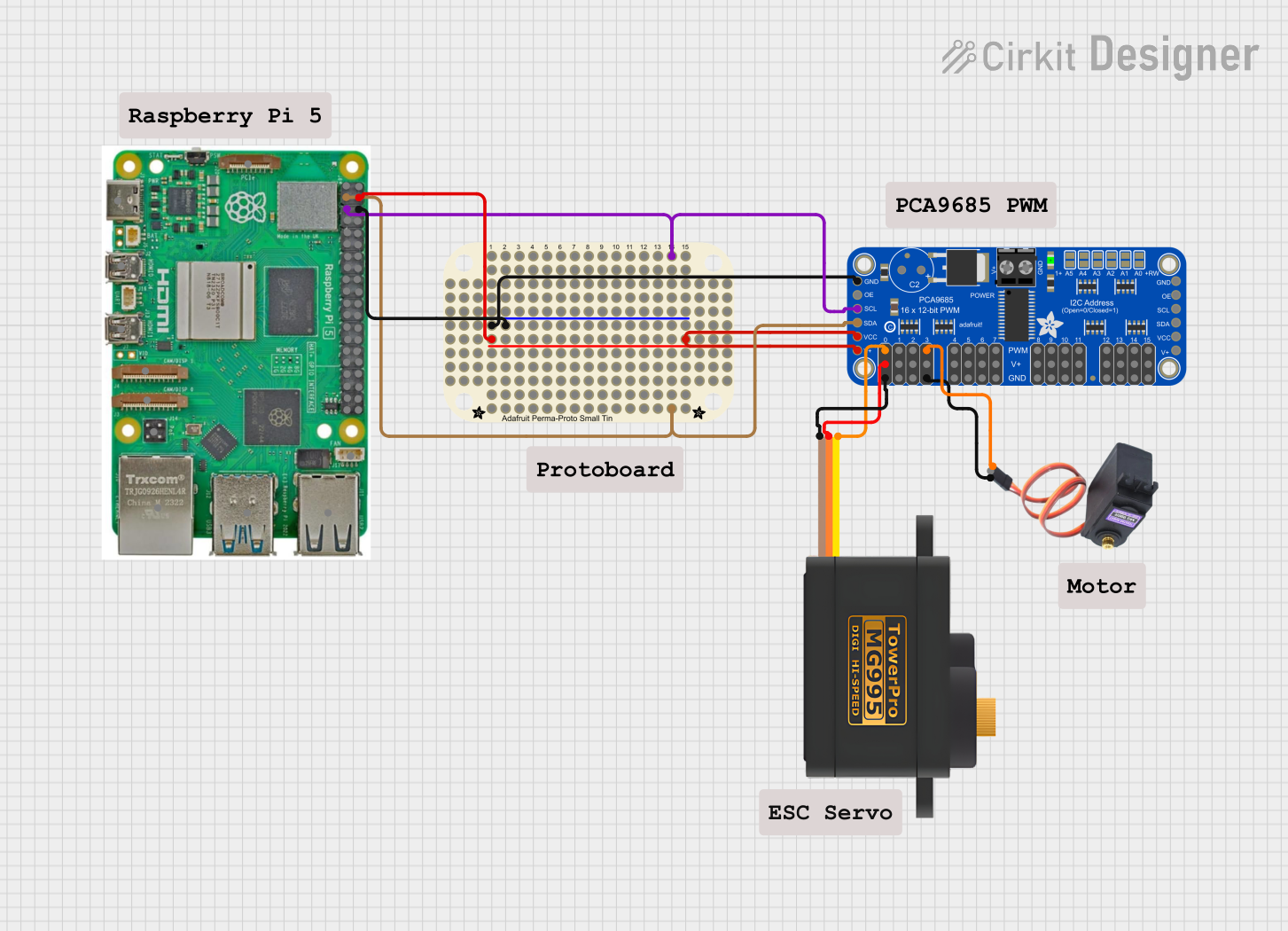
How to Use the PCA9685 in a Circuit

  1. Powering the PCA9685:

    • Connect the VCC pin to a 3.3V or 5V power source.
    • Connect the GND pin to the ground of your circuit.
    • If driving servos or LEDs, connect an external power source to the V+ pin.
  2. I2C Communication:

    • Connect the SDA and SCL pins to the corresponding I2C pins on your microcontroller.
    • Use pull-up resistors (typically 4.7kΩ) on the SDA and SCL lines if not already present.
  3. Configuring the I2C Address:

    • Set the address pins (A0–A5) to either HIGH or LOW to configure the I2C address.
    • The default address is 0x40 when all address pins are LOW.
  4. Connecting Outputs:

    • Connect servos, LEDs, or other devices to the OUT0–OUT15 pins.
    • Ensure the total current draw does not exceed the PCA9685's limits.
  5. Programming the PCA9685:

    • Use an I2C library to communicate with the PCA9685.
    • Set the PWM frequency and duty cycle for each channel as needed.

Example Code for Arduino UNO

Below is an example of how to control servos using the PCA9685 with an Arduino UNO:

#include <Wire.h>
#include <Adafruit_PWMServoDriver.h>

// Create an instance of the PCA9685 driver
Adafruit_PWMServoDriver pwm = Adafruit_PWMServoDriver();

void setup() {
  // Initialize serial communication for debugging
  Serial.begin(9600);
  Serial.println("Initializing PCA9685...");

  // Initialize the PCA9685
  pwm.begin();
  pwm.setPWMFreq(50); // Set PWM frequency to 50 Hz for servos
}

void loop() {
  // Example: Move a servo connected to channel 0
  int servoMin = 150; // Minimum pulse length (adjust for your servo)
  int servoMax = 600; // Maximum pulse length (adjust for your servo)

  // Sweep the servo from minimum to maximum position
  for (int pulse = servoMin; pulse <= servoMax; pulse++) {
    pwm.setPWM(0, 0, pulse); // Channel 0, start at 0, pulse width
    delay(10); // Small delay for smooth movement
  }

  // Sweep the servo back to the minimum position
  for (int pulse = servoMax; pulse >= servoMin; pulse--) {
    pwm.setPWM(0, 0, pulse);
    delay(10);
  }
}

Important Considerations

  • Use an external power supply for V+ when driving high-current devices like servos or LEDs.
  • Ensure the total current draw does not exceed the PCA9685's maximum ratings.
  • Use decoupling capacitors near the VCC and V+ pins to reduce noise.

Troubleshooting and FAQs

Common Issues and Solutions

  1. No Response from the PCA9685:

    • Verify the I2C connections (SDA, SCL) and ensure pull-up resistors are present.
    • Check the I2C address configuration and ensure it matches your code.
  2. Servos or LEDs Not Working:

    • Ensure the external power supply (V+) is connected and sufficient for your devices.
    • Verify the PWM frequency and pulse width settings in your code.
  3. Flickering LEDs or Erratic Servo Movement:

    • Add decoupling capacitors near the V+ pin to stabilize the power supply.
    • Check for loose or poor connections in the circuit.
  4. Overheating:

    • Ensure the total current draw does not exceed the PCA9685's limits.
    • Use a heatsink or active cooling if necessary.

FAQs

  • Can I use multiple PCA9685 modules in one project? Yes, you can connect up to 62 PCA9685 modules on the same I2C bus by configuring their addresses.

  • What is the maximum PWM frequency? The PCA9685 supports PWM frequencies up to 1526 Hz.

  • Can I use the PCA9685 with a 3.3V microcontroller? Yes, the PCA9685 is compatible with both 3.3V and 5V logic levels.

  • Do I need an external clock source? No, the PCA9685 has an internal oscillator, but you can use an external clock if higher precision is required.