Cirkit Designer Logo
Cirkit Designer
Your all-in-one circuit design IDE
Home / 
Component Documentation

How to Use Ra-01S: Examples, Pinouts, and Specs
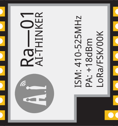

Image of Ra-01S
Cirkit Designer LogoDesign with Ra-01S in Cirkit Designer

Introduction

The Ra-01S is a resistor designed for use in electronic circuits to control current flow, divide voltages, and provide biasing for active components such as transistors and operational amplifiers. It is a passive component that plays a critical role in ensuring the proper functioning of circuits by maintaining desired voltage and current levels. The Ra-01S is characterized by its resistance value, power rating, and tolerance, making it suitable for a wide range of applications.

Explore Projects Built with Ra-01S

Use Cirkit Designer to design, explore, and prototype these projects online. Some projects support real-time simulation. Click "Open Project" to start designing instantly!
Satellite-Based Timing and Navigation System with SDR and Atomic Clock Synchronization
Image of GPS 시스템 측정 구성도_Confirm: A project utilizing Ra-01S in a practical application
This circuit appears to be a complex system involving power supply management, GPS and timing synchronization, and data communication. It includes a SI-TEX G1 Satellite Compass for GPS data, an XHTF1021 Atomic Rubidium Clock for precise timing, and Ettus USRP B200 units for software-defined radio communication. Power is supplied through various SMPS units and distributed via terminal blocks and DC jacks. Data communication is facilitated by Beelink MINI S12 N95 computers, RS232 splitters, and a 1000BASE-T Media Converter for network connectivity. RF Directional Couplers are used to interface antennas with the USRP units, and the entire system is likely contained within cases for protection and organization.
Cirkit Designer LogoOpen Project in Cirkit Designer
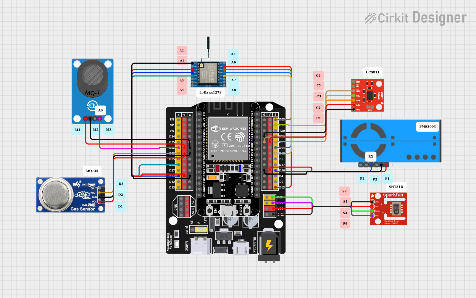
ESP32-Based Air Quality Monitoring System with LoRa Communication
Image of Esquema_Proyect_Grade: A project utilizing Ra-01S in a practical application
This circuit is designed for environmental monitoring, featuring a collection of sensors interfaced with an ESP32 microcontroller. It includes a LoRa Ra-02 SX1278 module for long-range communication, various air quality sensors (CCS811, PMS5003, MQ6, MQ-7) for detecting pollutants and gases, and an SHT1x sensor for measuring temperature and humidity. The ESP32 collects sensor data and can transmit it wirelessly via LoRa, enabling remote air quality and climate monitoring.
Cirkit Designer LogoOpen Project in Cirkit Designer
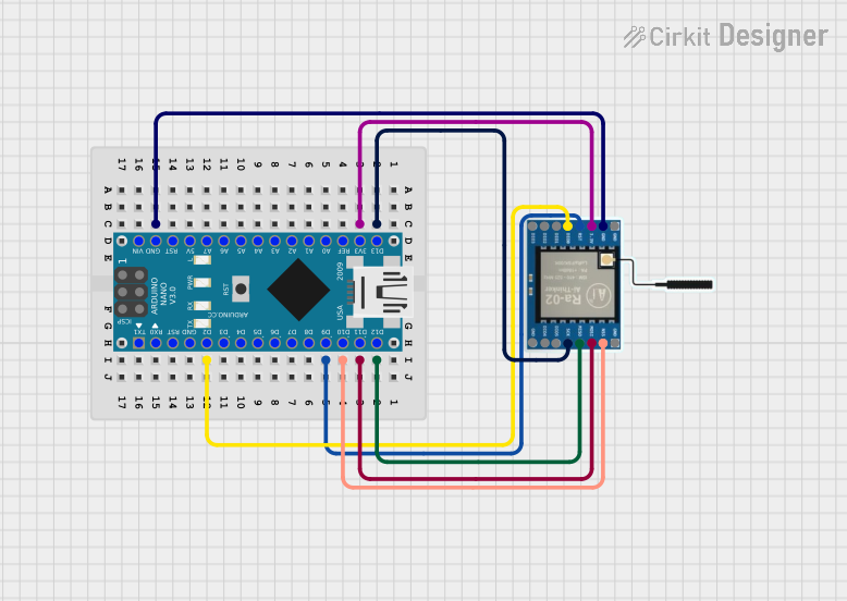
Arduino Nano and LoRa SX1278 Wireless Communication Module
Image of CSE216L Project Livestock Health Monitoring Secondary Circuit: A project utilizing Ra-01S in a practical application
This circuit consists of an Arduino Nano microcontroller connected to a LoRa Ra-02 SX1278 module, enabling wireless communication. The Arduino handles the SPI communication with the LoRa module, with connections for SCK, MISO, MOSI, NSS, and RST, as well as power and ground connections. This setup is typically used for long-range, low-power wireless data transmission.
Cirkit Designer LogoOpen Project in Cirkit Designer
Satellite Compass and Network-Integrated GPS Data Processing System
Image of GPS 시스템 측정 구성도_241016: A project utilizing Ra-01S in a practical application
This circuit comprises a satellite compass, a mini PC, two GPS antennas, power supplies, a network switch, media converters, and an atomic rubidium clock. The satellite compass is powered by a triple output DC power supply and interfaces with an RS232 splitter for 1PPS signals. The mini PCs are connected to the USRP B200 devices via USB for data and power, and to media converters via Ethernet, which in turn connect to a network switch using fiber optic links. The antennas are connected to the USRP B200s through RF directional couplers, and the atomic clock provides a 1PPS input to the RS232 splitter.
Cirkit Designer LogoOpen Project in Cirkit Designer

Explore Projects Built with Ra-01S

Use Cirkit Designer to design, explore, and prototype these projects online. Some projects support real-time simulation. Click "Open Project" to start designing instantly!
Image of GPS 시스템 측정 구성도_Confirm: A project utilizing Ra-01S in a practical application
Satellite-Based Timing and Navigation System with SDR and Atomic Clock Synchronization
This circuit appears to be a complex system involving power supply management, GPS and timing synchronization, and data communication. It includes a SI-TEX G1 Satellite Compass for GPS data, an XHTF1021 Atomic Rubidium Clock for precise timing, and Ettus USRP B200 units for software-defined radio communication. Power is supplied through various SMPS units and distributed via terminal blocks and DC jacks. Data communication is facilitated by Beelink MINI S12 N95 computers, RS232 splitters, and a 1000BASE-T Media Converter for network connectivity. RF Directional Couplers are used to interface antennas with the USRP units, and the entire system is likely contained within cases for protection and organization.
Cirkit Designer LogoOpen Project in Cirkit Designer
Image of Esquema_Proyect_Grade: A project utilizing Ra-01S in a practical application
ESP32-Based Air Quality Monitoring System with LoRa Communication
This circuit is designed for environmental monitoring, featuring a collection of sensors interfaced with an ESP32 microcontroller. It includes a LoRa Ra-02 SX1278 module for long-range communication, various air quality sensors (CCS811, PMS5003, MQ6, MQ-7) for detecting pollutants and gases, and an SHT1x sensor for measuring temperature and humidity. The ESP32 collects sensor data and can transmit it wirelessly via LoRa, enabling remote air quality and climate monitoring.
Cirkit Designer LogoOpen Project in Cirkit Designer
Image of CSE216L Project Livestock Health Monitoring Secondary Circuit: A project utilizing Ra-01S in a practical application
Arduino Nano and LoRa SX1278 Wireless Communication Module
This circuit consists of an Arduino Nano microcontroller connected to a LoRa Ra-02 SX1278 module, enabling wireless communication. The Arduino handles the SPI communication with the LoRa module, with connections for SCK, MISO, MOSI, NSS, and RST, as well as power and ground connections. This setup is typically used for long-range, low-power wireless data transmission.
Cirkit Designer LogoOpen Project in Cirkit Designer
Image of GPS 시스템 측정 구성도_241016: A project utilizing Ra-01S in a practical application
Satellite Compass and Network-Integrated GPS Data Processing System
This circuit comprises a satellite compass, a mini PC, two GPS antennas, power supplies, a network switch, media converters, and an atomic rubidium clock. The satellite compass is powered by a triple output DC power supply and interfaces with an RS232 splitter for 1PPS signals. The mini PCs are connected to the USRP B200 devices via USB for data and power, and to media converters via Ethernet, which in turn connect to a network switch using fiber optic links. The antennas are connected to the USRP B200s through RF directional couplers, and the atomic clock provides a 1PPS input to the RS232 splitter.
Cirkit Designer LogoOpen Project in Cirkit Designer

Common Applications and Use Cases

  • Current limiting in LED circuits
  • Voltage division in sensor interfaces
  • Biasing transistors in amplifier circuits
  • Pull-up or pull-down resistors in digital circuits
  • Filtering and signal conditioning in analog circuits

Technical Specifications

Key Technical Details

Parameter Value/Range
Resistance Value 10 Ω to 1 MΩ (varies by model)
Power Rating 0.25 W (1/4 W)
Tolerance ±1% (standard)
Temperature Coefficient ±100 ppm/°C
Operating Temperature -55°C to +155°C
Package Type Axial Lead

Pin Configuration and Descriptions

The Ra-01S is a two-terminal component with no polarity. The leads are used to connect the resistor in series or parallel configurations within a circuit.

Pin Number Description
Lead 1 Connects to one side of the circuit
Lead 2 Connects to the other side of the circuit

Usage Instructions

How to Use the Ra-01S in a Circuit

  1. Determine the Required Resistance Value: Use Ohm's Law (V = IR) to calculate the resistance needed for your application.
  2. Select the Appropriate Power Rating: Ensure the resistor's power rating exceeds the power it will dissipate in the circuit. Power dissipation is calculated as ( P = I^2R ) or ( P = V^2/R ).
  3. Insert the Resistor: Place the Ra-01S in the circuit, ensuring proper connection to the desired nodes. Since it is non-polarized, orientation does not matter.
  4. Solder the Leads: If using a PCB, solder the leads securely to the board. Trim excess lead length if necessary.
  5. Verify the Circuit: Use a multimeter to confirm the resistance value and ensure proper connections.

Important Considerations and Best Practices

  • Avoid exceeding the resistor's power rating to prevent overheating or damage.
  • Use resistors with a tolerance that meets the precision requirements of your application.
  • For high-frequency circuits, consider the resistor's parasitic inductance and capacitance.
  • Store resistors in a dry environment to prevent corrosion of the leads.

Example: Using the Ra-01S with an Arduino UNO

The Ra-01S can be used as a current-limiting resistor for an LED connected to an Arduino UNO. Below is an example circuit and code:

Circuit Description

  • Connect one lead of the Ra-01S (e.g., 220 Ω) to a digital pin on the Arduino (e.g., pin 13).
  • Connect the other lead of the resistor to the anode (+) of the LED.
  • Connect the cathode (-) of the LED to the Arduino's GND pin.

Arduino Code

// This code blinks an LED connected to pin 13 with a current-limiting resistor.

const int ledPin = 13; // Pin connected to the LED through the Ra-01S resistor

void setup() {
  pinMode(ledPin, OUTPUT); // Set pin 13 as an output
}

void loop() {
  digitalWrite(ledPin, HIGH); // Turn the LED on
  delay(1000);               // Wait for 1 second
  digitalWrite(ledPin, LOW);  // Turn the LED off
  delay(1000);               // Wait for 1 second
}

Troubleshooting and FAQs

Common Issues

  1. Resistor Overheating:

    • Cause: Exceeding the power rating of the resistor.
    • Solution: Use a resistor with a higher power rating or reduce the current through the resistor.
  2. Incorrect Resistance Value:

    • Cause: Misreading the color code or using the wrong resistor.
    • Solution: Double-check the resistor's color code or measure its resistance with a multimeter.
  3. Circuit Not Functioning as Expected:

    • Cause: Poor soldering or loose connections.
    • Solution: Inspect and re-solder connections if necessary.
  4. LED Not Lighting Up in Arduino Circuit:

    • Cause: Incorrect resistor value or reversed LED polarity.
    • Solution: Verify the resistor value and ensure the LED is connected with the correct polarity.

FAQs

Q: Can I use the Ra-01S in high-power applications?
A: The Ra-01S is rated for 0.25 W. For high-power applications, use a resistor with a higher power rating.

Q: How do I calculate the resistance value using the color code?
A: Use the standard resistor color code chart. The first two bands represent significant digits, the third band is the multiplier, and the fourth band indicates tolerance.

Q: Is the Ra-01S suitable for AC circuits?
A: Yes, the Ra-01S can be used in both AC and DC circuits, provided its power rating and resistance value are appropriate for the application.