How to Use LM2596: Examples, Pinouts, and Specs
Introduction
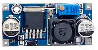
The LM2596 is a step-down (buck) voltage regulator designed to efficiently convert a higher input voltage into a stable, regulated output voltage. Manufactured under the part ID LM2596, this component is capable of delivering up to 3A of output current, making it ideal for applications requiring moderate power levels. Its wide input voltage range and high efficiency make it a popular choice for power supply circuits in embedded systems, industrial equipment, and consumer electronics.
Explore Projects Built with LM2596


Explore Projects Built with LM2596
Common Applications and Use Cases
- DC-DC power supply modules
- Battery-powered devices
- Voltage regulation for microcontrollers and sensors
- LED drivers
- Industrial automation systems
Technical Specifications
The LM2596 is available in fixed output voltage versions (e.g., 3.3V, 5V, 12V) as well as an adjustable version. Below are the key technical details:
| Parameter | Value |
|---|---|
| Input Voltage Range | 4.5V to 40V |
| Output Voltage Range | 1.23V to 37V (adjustable version) |
| Output Current | Up to 3A |
| Efficiency | Up to 90% |
| Switching Frequency | 150 kHz (typical) |
| Operating Temperature Range | -40°C to +125°C |
| Package Type | TO-220, TO-263 (surface-mount) |
Pin Configuration and Descriptions
The LM2596 typically comes in a 5-pin TO-220 or TO-263 package. Below is the pinout description:
| Pin Number | Pin Name | Description |
|---|---|---|
| 1 | VIN | Input voltage pin. Connect to the unregulated DC input voltage. |
| 2 | Output | Regulated output voltage pin. Connect to the load. |
| 3 | Ground (GND) | Ground pin. Connect to the circuit ground. |
| 4 | Feedback | Feedback pin. Used to set the output voltage (adjustable version only). |
| 5 | ON/OFF | Enable pin. Logic high enables the regulator; logic low disables it (optional). |
Usage Instructions
How to Use the LM2596 in a Circuit
- Input Voltage: Ensure the input voltage (VIN) is within the range of 4.5V to 40V. For optimal performance, the input voltage should be at least 3V higher than the desired output voltage.
- Output Voltage: For fixed versions, the output voltage is pre-set (e.g., 5V). For the adjustable version, use a resistor divider network connected to the Feedback pin to set the desired output voltage.
- Capacitors: Place input and output capacitors close to the regulator to ensure stability and reduce noise. Typical values are:
- Input capacitor: 100 µF electrolytic
- Output capacitor: 220 µF electrolytic
- Inductor Selection: Choose an inductor with a current rating higher than the maximum output current (e.g., 3.5A) and an appropriate inductance value (e.g., 33 µH for 5V output).
- Diode: Use a Schottky diode (e.g., 1N5822) rated for at least 3A and a reverse voltage higher than the input voltage.
Example Circuit
Below is a basic circuit for the adjustable version of the LM2596:
VIN ----+---- Input Capacitor ----+---- LM2596 (VIN Pin)
        |                         |
       GND                       GND
Arduino Example Code
The LM2596 can be used to power an Arduino UNO. Below is an example code snippet to demonstrate its use:
// Example: Reading a sensor powered by LM2596 regulator
// Ensure the LM2596 output is set to 5V for Arduino UNO

const int sensorPin = A0; // Analog pin connected to the sensor
int sensorValue = 0;      // Variable to store sensor reading

void setup() {
  Serial.begin(9600); // Initialize serial communication
}

void loop() {
  sensorValue = analogRead(sensorPin); // Read sensor value
  Serial.print("Sensor Value: ");
  Serial.println(sensorValue); // Print sensor value to Serial Monitor
  delay(1000); // Wait for 1 second
}
Important Considerations and Best Practices
- Always use a heat sink or proper ventilation if the LM2596 operates near its maximum current rating (3A).
- Use low-ESR capacitors to improve stability and reduce output ripple.
- Avoid exceeding the maximum input voltage (40V) to prevent damage to the regulator.
- For the adjustable version, calculate the resistor divider values using the formula: [ V_{OUT} = V_{REF} \times \left(1 + \frac{R_2}{R_1}\right) ] where ( V_{REF} = 1.23V ).
Troubleshooting and FAQs
Common Issues and Solutions
Output Voltage is Incorrect
- Check the resistor divider network (for adjustable version).
- Verify the input voltage is at least 3V higher than the desired output voltage.
Excessive Heat
- Ensure the load current does not exceed 3A.
- Use a heat sink or improve airflow around the regulator.
High Output Ripple
- Use low-ESR capacitors on the input and output.
- Verify the inductor value is appropriate for the output voltage.
No Output Voltage
- Check the ON/OFF pin. Ensure it is connected to logic high or left floating.
- Verify all connections and ensure the input voltage is within range.
FAQs
Q: Can the LM2596 be used for negative voltage regulation?
A: No, the LM2596 is designed for positive voltage regulation only.
Q: What is the maximum efficiency of the LM2596?
A: The LM2596 can achieve up to 90% efficiency under optimal conditions.
Q: Can I use the LM2596 without an inductor?
A: No, an inductor is essential for the buck converter operation. Without it, the regulator will not function properly.
Q: Is the LM2596 suitable for powering sensitive analog circuits?
A: While the LM2596 is efficient, its output ripple may affect sensitive analog circuits. Use additional filtering if necessary.