How to Use 12v to 5v Convertor: Examples, Pinouts, and Specs
Introduction
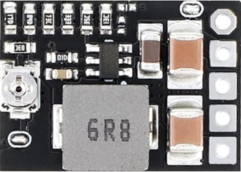
The Drok 12V to 5V Converter (Part ID: 5v12v) is a compact and efficient step-down voltage regulator designed to convert a 12V DC input to a stable 5V DC output. This component is widely used in applications where 5V devices, such as microcontrollers, sensors, or USB-powered devices, need to be powered from a 12V power source, such as a car battery or solar panel system.
Explore Projects Built with 12v to 5v Convertor


Explore Projects Built with 12v to 5v Convertor
Common Applications
- Powering 5V microcontrollers (e.g., Arduino, Raspberry Pi) from a 12V source.
- Supplying power to USB devices in automotive or industrial environments.
- Integrating with 12V solar systems to power 5V peripherals.
- General-purpose voltage regulation in embedded systems.
Technical Specifications
The following table outlines the key technical details of the Drok 12V to 5V Converter:
| Parameter | Specification |
|---|---|
| Input Voltage Range | 8V to 22V DC |
| Output Voltage | 5V DC ± 0.1V |
| Maximum Output Current | 3A |
| Efficiency | Up to 96% |
| Operating Temperature | -40°C to +85°C |
| Dimensions | 46mm x 27mm x 14mm |
| Weight | 20g |
| Protection Features | Overcurrent, Overvoltage, Overheat |
Pin Configuration and Descriptions
The Drok 12V to 5V Converter has four connection points, as described in the table below:
| Pin | Label | Description |
|---|---|---|
| 1 | VIN+ | Positive input terminal for 12V DC power source. |
| 2 | VIN- | Negative input terminal (ground) for 12V DC source. |
| 3 | VOUT+ | Positive output terminal for 5V DC power. |
| 4 | VOUT- | Negative output terminal (ground) for 5V DC power. |
Usage Instructions
How to Use the Component in a Circuit
- Connect the Input:
- Attach the VIN+ pin to the positive terminal of your 12V DC power source.
- Connect the VIN- pin to the ground terminal of your 12V DC power source.
- Connect the Output:
- Attach the VOUT+ pin to the positive terminal of your 5V device.
- Connect the VOUT- pin to the ground terminal of your 5V device.
- Verify Connections:
- Double-check all connections to ensure proper polarity and secure wiring.
- Power On:
- Turn on the 12V power source. The converter will step down the voltage to 5V and supply it to the connected device.
Important Considerations and Best Practices
- Heat Dissipation: Ensure adequate ventilation or heat sinking if the converter operates near its maximum current rating (3A).
- Input Voltage Range: Do not exceed the input voltage range (8V to 22V) to avoid damaging the converter.
- Polarity: Always observe correct polarity for both input and output connections.
- Load Requirements: Ensure the connected 5V device does not exceed the maximum output current of 3A.
Example: Using with an Arduino UNO
The Drok 12V to 5V Converter can be used to power an Arduino UNO from a 12V source. Below is an example wiring and code:
Wiring
- Connect the VIN+ pin of the converter to the positive terminal of a 12V battery.
- Connect the VIN- pin of the converter to the negative terminal of the battery.
- Connect the VOUT+ pin of the converter to the 5V pin of the Arduino UNO.
- Connect the VOUT- pin of the converter to the GND pin of the Arduino UNO.
Code Example
// Example code to blink an LED on pin 13 of the Arduino UNO
// Ensure the Arduino is powered via the 5V pin from the Drok converter

void setup() {
  pinMode(13, OUTPUT); // Set pin 13 as an output
}

void loop() {
  digitalWrite(13, HIGH); // Turn the LED on
  delay(1000);            // Wait for 1 second
  digitalWrite(13, LOW);  // Turn the LED off
  delay(1000);            // Wait for 1 second
}
Troubleshooting and FAQs
Common Issues and Solutions
No Output Voltage:
- Cause: Incorrect wiring or loose connections.
- Solution: Verify all connections, ensuring correct polarity and secure wiring.
Overheating:
- Cause: Operating near or above the maximum current rating (3A).
- Solution: Reduce the load or improve heat dissipation with a heatsink or better ventilation.
Output Voltage Fluctuations:
- Cause: Input voltage instability or excessive load.
- Solution: Ensure the input voltage is stable and within the specified range. Reduce the load if necessary.
Device Not Powering On:
- Cause: Insufficient current supply or incorrect connections.
- Solution: Check the current requirements of the connected device and ensure proper wiring.
FAQs
Q: Can I use this converter with a 24V power source?
A: No, the maximum input voltage is 22V. Using a 24V source may damage the converter.
Q: Is the output voltage adjustable?
A: No, the output voltage is fixed at 5V.
Q: Can I use this converter to charge a USB device?
A: Yes, as long as the device's current requirements do not exceed 3A.
Q: Does the converter have reverse polarity protection?
A: No, ensure correct polarity to avoid damage to the converter.