How to Use W23Q128FV serial Flash Memory: Examples, Pinouts, and Specs
Introduction
The W23Q128FV is a high-performance serial Flash memory device with a storage capacity of 128 megabits (16 megabytes). It utilizes a Serial Peripheral Interface (SPI) for fast and efficient data transfer. This component is widely used in applications such as embedded systems, consumer electronics, and automotive devices for reliable data storage and retrieval. Its compact design and robust performance make it an ideal choice for systems requiring non-volatile memory.
Explore Projects Built with W23Q128FV serial Flash Memory


Explore Projects Built with W23Q128FV serial Flash Memory
Common Applications
- Embedded systems for firmware storage
- Consumer electronics (e.g., smart TVs, set-top boxes)
- Automotive systems for data logging
- IoT devices for configuration and data storage
- Industrial control systems
Technical Specifications
Key Specifications
| Parameter | Value |
|---|---|
| Memory Capacity | 128 Mbit (16 MB) |
| Interface | SPI (Serial Peripheral Interface) |
| Operating Voltage | 2.7V to 3.6V |
| Maximum Clock Frequency | 133 MHz |
| Page Size | 256 bytes |
| Sector Size | 4 KB |
| Block Size | 64 KB |
| Endurance | 100,000 program/erase cycles |
| Data Retention | 20 years |
| Operating Temperature | -40°C to +85°C |
| Package Options | SOP-8, WSON-8, USON-8 |
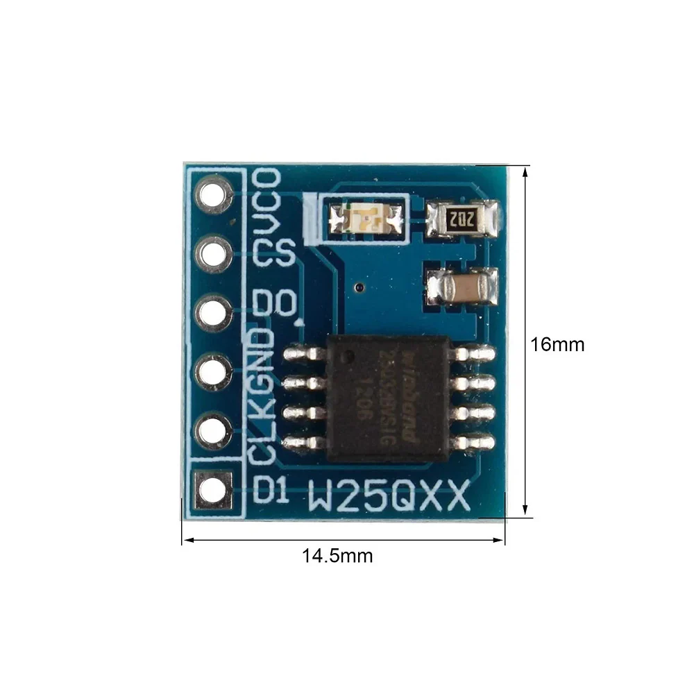
Pin Configuration and Descriptions
The W23Q128FV is typically available in an 8-pin package. Below is the pinout and description:
| Pin Number | Pin Name | Description |
|---|---|---|
| 1 | CS# | Chip Select (active low) |
| 2 | DO (MISO) | Data Output (Master In Slave Out) |
| 3 | WP# | Write Protect (active low) |
| 4 | GND | Ground |
| 5 | DI (MOSI) | Data Input (Master Out Slave In) |
| 6 | CLK | Serial Clock |
| 7 | HOLD# | Hold (active low) |
| 8 | VCC | Power Supply (2.7V to 3.6V) |
Usage Instructions
How to Use the W23Q128FV in a Circuit
- Power Supply: Connect the VCC pin to a 3.3V power source and the GND pin to ground.
- SPI Interface: Connect the SPI pins (CS#, CLK, DI, DO) to the corresponding SPI pins on your microcontroller or processor.
- Write Protect: If write protection is not required, connect the WP# pin to VCC.
- Hold Function: If the hold function is not used, connect the HOLD# pin to VCC.
- Pull-up Resistors: Use pull-up resistors on the CS#, WP#, and HOLD# pins if required by your design.
Important Considerations
- Ensure the SPI clock frequency does not exceed 133 MHz.
- Use decoupling capacitors (e.g., 0.1 µF) near the VCC pin to stabilize the power supply.
- Avoid exceeding the maximum program/erase cycles to maintain data integrity.
- Use proper ESD protection when handling the component.
Example: Connecting to an Arduino UNO
The W23Q128FV can be interfaced with an Arduino UNO using its SPI pins. Below is an example circuit connection and code:
Circuit Connections
| W23Q128FV Pin | Arduino UNO Pin |
|---|---|
| CS# | Pin 10 |
| DO (MISO) | Pin 12 |
| DI (MOSI) | Pin 11 |
| CLK | Pin 13 |
| GND | GND |
| VCC | 3.3V |
| WP# | 3.3V |
| HOLD# | 3.3V |
Example Code
#include <SPI.h>

// Define SPI pins for the W23Q128FV
const int CS_PIN = 10;

void setup() {
  // Initialize serial communication for debugging
  Serial.begin(9600);

  // Set up SPI and chip select pin
  pinMode(CS_PIN, OUTPUT);
  digitalWrite(CS_PIN, HIGH); // Deselect the chip
  SPI.begin();

  // Test communication with the W23Q128FV
  Serial.println("Initializing W23Q128FV...");
  if (readDeviceID()) {
    Serial.println("Device ID read successfully!");
  } else {
    Serial.println("Failed to read Device ID.");
  }
}

void loop() {
  // Main loop can include read/write operations
}

// Function to read the Device ID of the W23Q128FV
bool readDeviceID() {
  digitalWrite(CS_PIN, LOW); // Select the chip
  SPI.transfer(0x9F);        // Send "Read ID" command

  // Read the 3-byte Device ID
  byte manufacturerID = SPI.transfer(0x00);
  byte memoryType = SPI.transfer(0x00);
  byte capacity = SPI.transfer(0x00);
  digitalWrite(CS_PIN, HIGH); // Deselect the chip

  // Print the Device ID
  Serial.print("Manufacturer ID: 0x");
  Serial.println(manufacturerID, HEX);
  Serial.print("Memory Type: 0x");
  Serial.println(memoryType, HEX);
  Serial.print("Capacity: 0x");
  Serial.println(capacity, HEX);

  // Check if the Device ID matches the W23Q128FV
  return (manufacturerID == 0xEF && memoryType == 0x40 && capacity == 0x18);
}
Troubleshooting and FAQs
Common Issues
Device Not Responding
- Cause: Incorrect SPI connections or chip select pin not properly configured.
- Solution: Double-check the wiring and ensure the CS# pin is correctly controlled.
Data Corruption
- Cause: Exceeding the maximum program/erase cycles or power instability.
- Solution: Monitor the program/erase cycles and use decoupling capacitors near the VCC pin.
Write Operations Failing
- Cause: WP# pin is active (low) or write protection is enabled.
- Solution: Ensure the WP# pin is connected to VCC and check the status register for write protection settings.
Incorrect Device ID
- Cause: SPI clock speed too high or incorrect initialization sequence.
- Solution: Reduce the SPI clock speed and verify the initialization code.
FAQs
Can the W23Q128FV operate at 5V?
- No, the W23Q128FV operates within a voltage range of 2.7V to 3.6V. Use a level shifter if interfacing with a 5V system.
What is the maximum data retention period?
- The W23Q128FV guarantees a data retention period of 20 years under normal operating conditions.
How do I erase a sector or block?
- Use the "Sector Erase" (0x20) or "Block Erase" (0xD8) commands via SPI. Refer to the datasheet for detailed instructions.
Is the W23Q128FV suitable for high-temperature environments?
- Yes, it operates within a temperature range of -40°C to +85°C, making it suitable for industrial and automotive applications.