Cirkit Designer
Your all-in-one circuit design IDE
Home /
Component Documentation
How to Use 8ch SSR: Examples, Pinouts, and Specs
Introduction
The 8-Channel Solid State Relay (SSR) is a versatile electronic component designed for switching multiple high-power devices with electrical isolation and no moving parts. Unlike mechanical relays, SSRs use semiconductor switching elements, which provide faster switching times, longer life, and silent operation. This makes them ideal for applications where reliability and noise reduction are critical.
Explore Projects Built with 8ch SSR
ESP32-Based Wi-Fi Controlled Servo Gate System with Pushbutton Activation
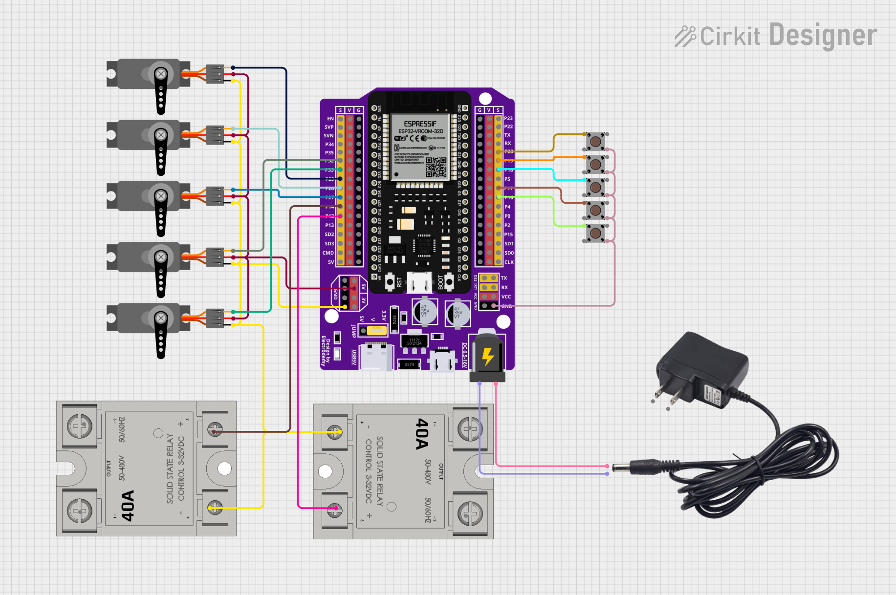
This circuit uses an ESP32 microcontroller to control five servos and two solid-state relays (SSRs) based on the state of five pushbuttons. The servos are used to open and close gates, while the SSRs control two motors, which are activated depending on the number of active gates.
ESP32-Based Vibration and Smoke Detection System with Web Control and Safety Indicators

This circuit is designed to monitor environmental conditions using a vibration sensor and a smoke detector, with the ability to control an exhaust fan and a DC motor via solid-state relays. The ESP32 microcontroller is programmed to provide web server functionality for remote monitoring and control, and uses LEDs as status indicators for different levels of alert. The power supply and step-down module ensure appropriate voltage levels for the components, and the SSRs are used to safely switch high-current loads like the fan and motor.
Temperature-Controlled Heating System with SSR and Titanium Resistor

This circuit is a temperature control system that uses a temperature controller to regulate a heating titanium resistor via a solid-state relay (SSR). The power transformer supplies the necessary voltage to the temperature controller, which in turn controls the SSR to manage the heating element.
Arduino-Controlled Multi-Stage Coin-Operated Car Wash System with LCD Display
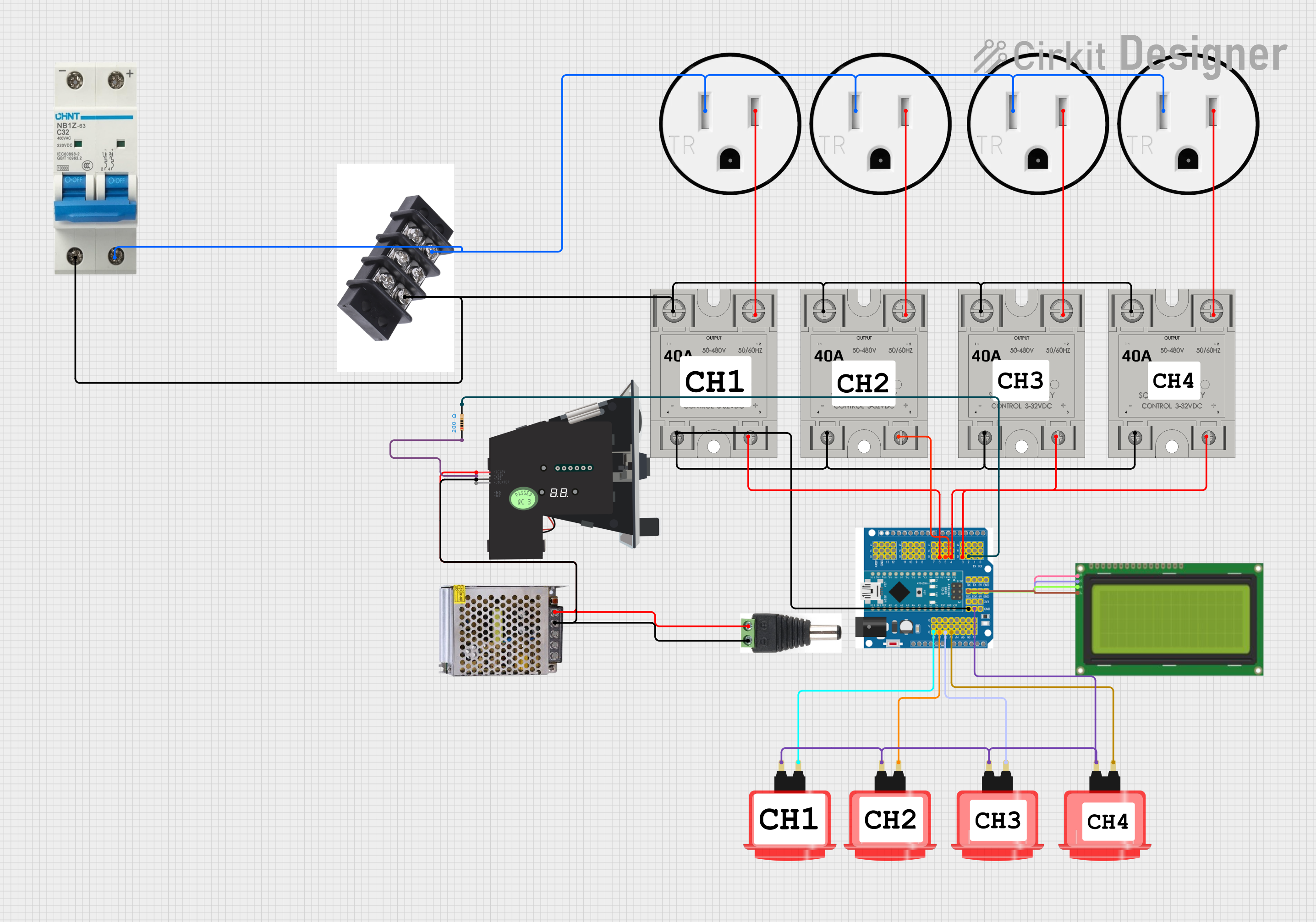
This circuit is a coin-operated control system for a multi-stage process, such as a car wash, managed by an Arduino microcontroller. It includes solid-state relays to control high-power devices, an LCD for user interface, and arcade buttons for user input. The system allows users to insert coins to activate different stages, with settings adjustable via a long-press menu.
Explore Projects Built with 8ch SSR
ESP32-Based Wi-Fi Controlled Servo Gate System with Pushbutton Activation
This circuit uses an ESP32 microcontroller to control five servos and two solid-state relays (SSRs) based on the state of five pushbuttons. The servos are used to open and close gates, while the SSRs control two motors, which are activated depending on the number of active gates.
ESP32-Based Vibration and Smoke Detection System with Web Control and Safety Indicators
This circuit is designed to monitor environmental conditions using a vibration sensor and a smoke detector, with the ability to control an exhaust fan and a DC motor via solid-state relays. The ESP32 microcontroller is programmed to provide web server functionality for remote monitoring and control, and uses LEDs as status indicators for different levels of alert. The power supply and step-down module ensure appropriate voltage levels for the components, and the SSRs are used to safely switch high-current loads like the fan and motor.
Temperature-Controlled Heating System with SSR and Titanium Resistor
This circuit is a temperature control system that uses a temperature controller to regulate a heating titanium resistor via a solid-state relay (SSR). The power transformer supplies the necessary voltage to the temperature controller, which in turn controls the SSR to manage the heating element.
Arduino-Controlled Multi-Stage Coin-Operated Car Wash System with LCD Display
This circuit is a coin-operated control system for a multi-stage process, such as a car wash, managed by an Arduino microcontroller. It includes solid-state relays to control high-power devices, an LCD for user interface, and arcade buttons for user input. The system allows users to insert coins to activate different stages, with settings adjustable via a long-press menu.
Common Applications and Use Cases
- Home Automation: Control lighting, heating, and other household appliances.
- Industrial Automation: Manage motors, pumps, and other heavy machinery.
- Robotics: Switch high-power actuators and motors.
- HVAC Systems: Control fans, compressors, and other components.
- IoT Projects: Integrate with microcontrollers like Arduino for smart home and industrial IoT applications.
Technical Specifications
Key Technical Details
| Parameter | Value |
|---|---|
| Operating Voltage | 5V DC (control side) |
| Load Voltage | 24-380V AC (output side) |
| Load Current | 2A per channel |
| Isolation Voltage | 2500V AC |
| Switching Time | ≤ 10ms |
| Operating Temperature | -30°C to 80°C |
| Dimensions | 138mm x 56mm x 25mm |
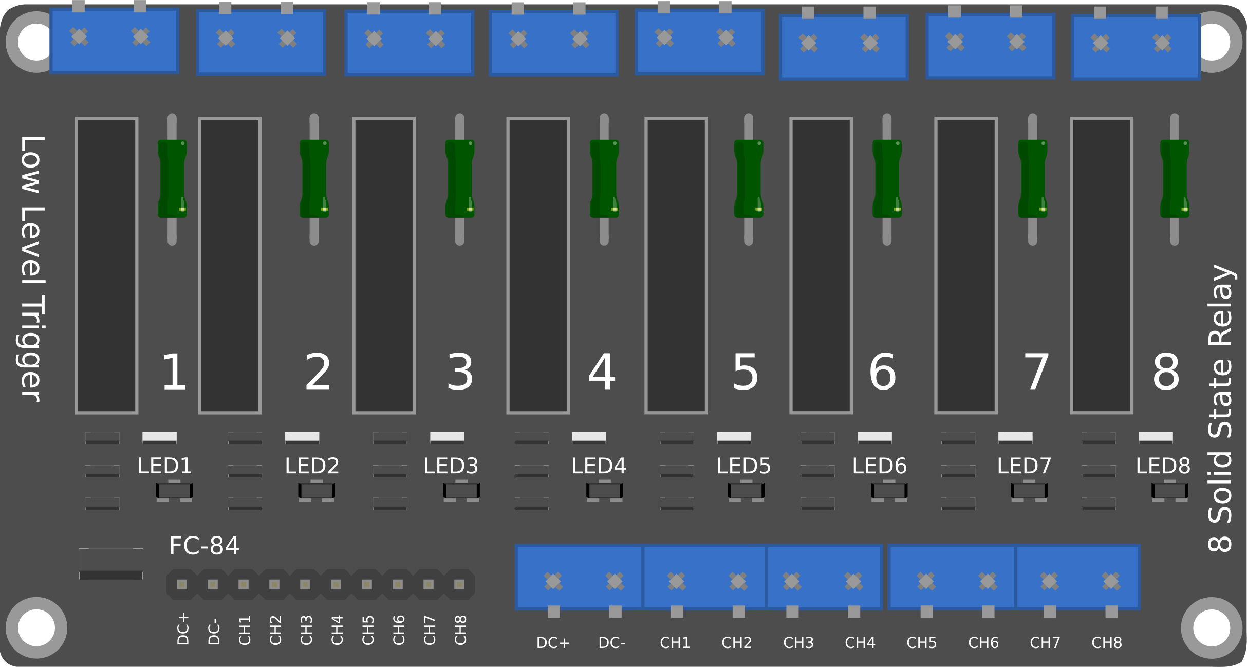
Pin Configuration and Descriptions
Control Side (Input)
| Pin Number | Pin Name | Description |
|---|---|---|
| 1 | IN1 | Control signal for Channel 1 |
| 2 | IN2 | Control signal for Channel 2 |
| 3 | IN3 | Control signal for Channel 3 |
| 4 | IN4 | Control signal for Channel 4 |
| 5 | IN5 | Control signal for Channel 5 |
| 6 | IN6 | Control signal for Channel 6 |
| 7 | IN7 | Control signal for Channel 7 |
| 8 | IN8 | Control signal for Channel 8 |
| 9 | GND | Ground |
| 10 | VCC | 5V DC power supply |
Load Side (Output)
| Channel | Terminal 1 | Terminal 2 | Description |
|---|---|---|---|
| 1 | NO1 | COM1 | Normally Open and Common for Channel 1 |
| 2 | NO2 | COM2 | Normally Open and Common for Channel 2 |
| 3 | NO3 | COM3 | Normally Open and Common for Channel 3 |
| 4 | NO4 | COM4 | Normally Open and Common for Channel 4 |
| 5 | NO5 | COM5 | Normally Open and Common for Channel 5 |
| 6 | NO6 | COM6 | Normally Open and Common for Channel 6 |
| 7 | NO7 | COM7 | Normally Open and Common for Channel 7 |
| 8 | NO8 | COM8 | Normally Open and Common for Channel 8 |
Usage Instructions
How to Use the Component in a Circuit
- Power Supply: Connect the VCC pin to a 5V DC power supply and the GND pin to the ground.
- Control Signals: Connect the control pins (IN1 to IN8) to the digital output pins of a microcontroller (e.g., Arduino).
- Load Connections: Connect the load terminals (NO1 to NO8 and COM1 to COM8) to the high-power devices you wish to control.
- Programming: Write a program to send control signals to the SSR channels.
Important Considerations and Best Practices
- Electrical Isolation: Ensure proper electrical isolation between the control side and the load side to prevent damage to the microcontroller.
- Heat Dissipation: SSRs can generate heat during operation. Ensure adequate ventilation or heat sinking.
- Load Ratings: Do not exceed the specified load voltage and current ratings to avoid damage.
- Inductive Loads: For inductive loads (e.g., motors), consider using snubber circuits to protect the SSR from voltage spikes.
Example Code for Arduino UNO
// Example code to control an 8-channel SSR with Arduino UNO

// Define control pins
const int ssrPins[8] = {2, 3, 4, 5, 6, 7, 8, 9};

void setup() {
  // Initialize control pins as outputs
  for (int i = 0; i < 8; i++) {
    pinMode(ssrPins[i], OUTPUT);
  }
}

void loop() {
  // Turn on all SSR channels
  for (int i = 0; i < 8; i++) {
    digitalWrite(ssrPins[i], HIGH);
    delay(1000); // Wait for 1 second
  }

  // Turn off all SSR channels
  for (int i = 0; i < 8; i++) {
    digitalWrite(ssrPins[i], LOW);
    delay(1000); // Wait for 1 second
  }
}
Troubleshooting and FAQs
Common Issues Users Might Face
SSR Not Switching:
- Solution: Check the control signal voltage. Ensure it is 5V DC.
- Solution: Verify the connections between the microcontroller and the SSR.
Overheating:
- Solution: Ensure proper ventilation or use a heat sink.
- Solution: Check the load current. Ensure it does not exceed 2A per channel.
Load Not Responding:
- Solution: Verify the load connections (NO and COM terminals).
- Solution: Check the load voltage and current ratings.
Solutions and Tips for Troubleshooting
- Multimeter Check: Use a multimeter to check the voltage levels at the control and load terminals.
- LED Indicators: Some SSR modules have LED indicators for each channel. Use these to verify the control signals.
- Code Debugging: Ensure the microcontroller code is correctly sending HIGH and LOW signals to the SSR control pins.
By following this documentation, users can effectively integrate and troubleshoot the 8-Channel Solid State Relay in their projects, ensuring reliable and efficient operation.