How to Use 5v fan: Examples, Pinouts, and Specs
Introduction
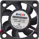
A 5V fan is a small electric fan that operates on a 5-volt power supply. It is widely used for cooling electronic components, such as microcontrollers, processors, and power regulators, or for providing ventilation in compact spaces. Due to its low power consumption and compact size, the 5V fan is ideal for applications in embedded systems, robotics, and DIY electronics projects.
Explore Projects Built with 5v fan


Explore Projects Built with 5v fan
Common Applications and Use Cases
- Cooling Raspberry Pi, Arduino, or other microcontroller boards
- Ventilation in small enclosures or cases
- Heat dissipation for power supplies and voltage regulators
- DIY projects requiring airflow in compact spaces
- Cooling 3D printer components or small motors
Technical Specifications
Below are the key technical details of a typical 5V fan:
| Parameter | Specification |
|---|---|
| Operating Voltage | 5V DC |
| Current Consumption | 80mA to 200mA (varies by model) |
| Power Consumption | 0.4W to 1W |
| Fan Speed | 3000 to 8000 RPM (varies by model) |
| Airflow | 2.5 to 10 CFM (Cubic Feet per Minute) |
| Noise Level | 20 to 30 dBA |
| Dimensions | Common sizes: 30x30mm, 40x40mm, 50x50mm |
| Connector Type | 2-pin or 3-pin JST or Dupont |
| Bearing Type | Sleeve or Ball Bearing |
| Lifespan | 20,000 to 50,000 hours |
Pin Configuration and Descriptions
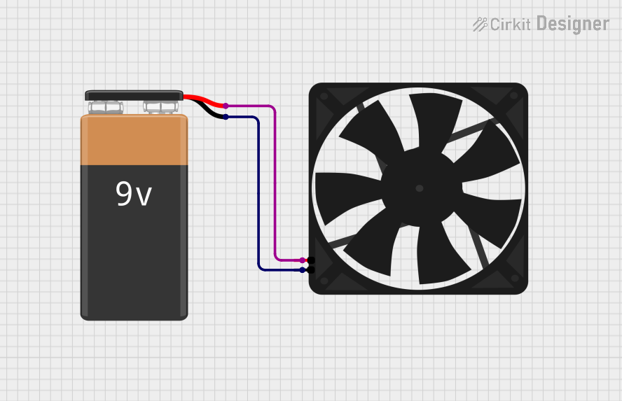
The 5V fan typically comes with a 2-pin or 3-pin connector. Below is the pin configuration:
2-Pin Connector
| Pin | Wire Color | Description |
|---|---|---|
| 1 | Red | Positive (+5V) |
| 2 | Black | Ground (GND) |
3-Pin Connector
| Pin | Wire Color | Description |
|---|---|---|
| 1 | Red | Positive (+5V) |
| 2 | Black | Ground (GND) |
| 3 | Yellow | Tachometer (Speed Signal) |
Usage Instructions
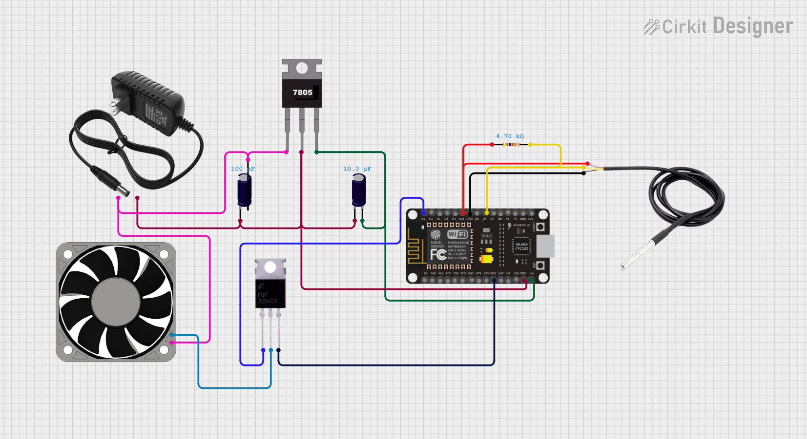
How to Use the 5V Fan in a Circuit
- Power Supply: Connect the red wire to a 5V DC power source and the black wire to ground (GND). Ensure the power source can supply sufficient current for the fan (e.g., 200mA).
- Optional Speed Monitoring: If using a 3-pin fan, connect the yellow wire to a microcontroller's input pin to monitor the fan's speed using the tachometer signal.
- Mounting: Secure the fan in place using screws or adhesive mounts. Ensure the airflow direction aligns with your cooling requirements (usually indicated by arrows on the fan housing).
Important Considerations and Best Practices
- Voltage Tolerance: Do not exceed the rated 5V input, as overvoltage can damage the fan.
- Current Supply: Ensure your power source can provide sufficient current to avoid underpowering the fan.
- Airflow Direction: Check the airflow direction (indicated by arrows on the fan) to ensure proper cooling.
- Noise Reduction: Use rubber mounts or grommets to reduce vibration and noise.
- Dust Accumulation: Periodically clean the fan blades to prevent dust buildup, which can reduce efficiency and increase noise.
Example: Connecting a 5V Fan to an Arduino UNO
Below is an example of how to control a 5V fan using an Arduino UNO and a transistor for switching:
// Example: Controlling a 5V fan with Arduino UNO
// The fan is connected to a transistor for switching.
// Pin 9 is used to control the fan.

const int fanPin = 9; // Pin connected to the transistor's base

void setup() {
  pinMode(fanPin, OUTPUT); // Set fanPin as an output
}

void loop() {
  digitalWrite(fanPin, HIGH); // Turn the fan ON
  delay(5000);               // Keep the fan ON for 5 seconds
  digitalWrite(fanPin, LOW);  // Turn the fan OFF
  delay(5000);               // Keep the fan OFF for 5 seconds
}
Circuit Notes:
- Use an NPN transistor (e.g., 2N2222) to switch the fan. Connect the fan's red wire to 5V and the black wire to the transistor's collector. The emitter should be connected to GND.
- Place a 1kΩ resistor between the Arduino pin and the transistor's base to limit current.
- Optionally, add a flyback diode (e.g., 1N4007) across the fan terminals to protect the circuit from voltage spikes.
Troubleshooting and FAQs
Common Issues and Solutions
Fan Not Spinning
- Cause: Insufficient power supply or incorrect wiring.
- Solution: Verify the power source provides 5V and sufficient current. Check the wiring for proper connections.
Fan Spins Slowly
- Cause: Insufficient current or high resistance in the circuit.
- Solution: Ensure the power source can supply the required current. Check for loose or corroded connections.
Excessive Noise
- Cause: Dust buildup or improper mounting.
- Solution: Clean the fan blades and ensure the fan is securely mounted with vibration-dampening materials.
Fan Overheats
- Cause: Prolonged operation at high temperatures or overvoltage.
- Solution: Ensure the fan operates within its rated voltage and ambient temperature range.
FAQs
Q1: Can I power a 5V fan with a USB port?
A1: Yes, most USB ports provide 5V and sufficient current (500mA or more) to power a 5V fan.
Q2: How do I reverse the airflow direction?
A2: To reverse airflow, physically flip the fan. Do not reverse the polarity of the power supply, as this can damage the fan.
Q3: Can I control the fan speed?
A3: Yes, you can control the fan speed using PWM (Pulse Width Modulation) from a microcontroller like Arduino. Use a transistor to handle the fan's current.
Q4: What is the purpose of the yellow wire on a 3-pin fan?
A4: The yellow wire provides a tachometer signal, which can be used to monitor the fan's speed.
Q5: Can I use a 5V fan with a 12V power supply?
A5: No, using a 12V power supply will damage the fan. Use a step-down voltage regulator to convert 12V to 5V if needed.