How to Use DS3231 RTC Breakout (Qwiic 2x): Examples, Pinouts, and Specs
Introduction
The DS3231 RTC Breakout (Qwiic 2x) by Adafruit is a highly accurate real-time clock (RTC) module designed to provide precise timekeeping and date information. It features a temperature-compensated crystal oscillator (TCXO) to ensure stability and accuracy, even under varying environmental conditions. The module communicates via the Qwiic interface, simplifying connections to microcontrollers and other devices.
This RTC module is ideal for applications requiring reliable timekeeping, such as:
- Data logging systems
- Alarm clocks
- Timed automation systems
- IoT devices with time-based triggers
- Calendar-based scheduling systems
Explore Projects Built with DS3231 RTC Breakout (Qwiic 2x)


Explore Projects Built with DS3231 RTC Breakout (Qwiic 2x)
Technical Specifications
The DS3231 RTC Breakout (Qwiic 2x) offers the following key specifications:
| Parameter | Value |
|---|---|
| Supply Voltage | 3.3V to 5.5V |
| Communication Interface | I2C (Qwiic-compatible) |
| I2C Address (Default) | 0x68 |
| Timekeeping Accuracy | ±2 ppm (0°C to +40°C) |
| Operating Temperature Range | -40°C to +85°C |
| Backup Battery Support | CR1220 coin cell (not included) |
| Dimensions | 25.5mm x 25.5mm |
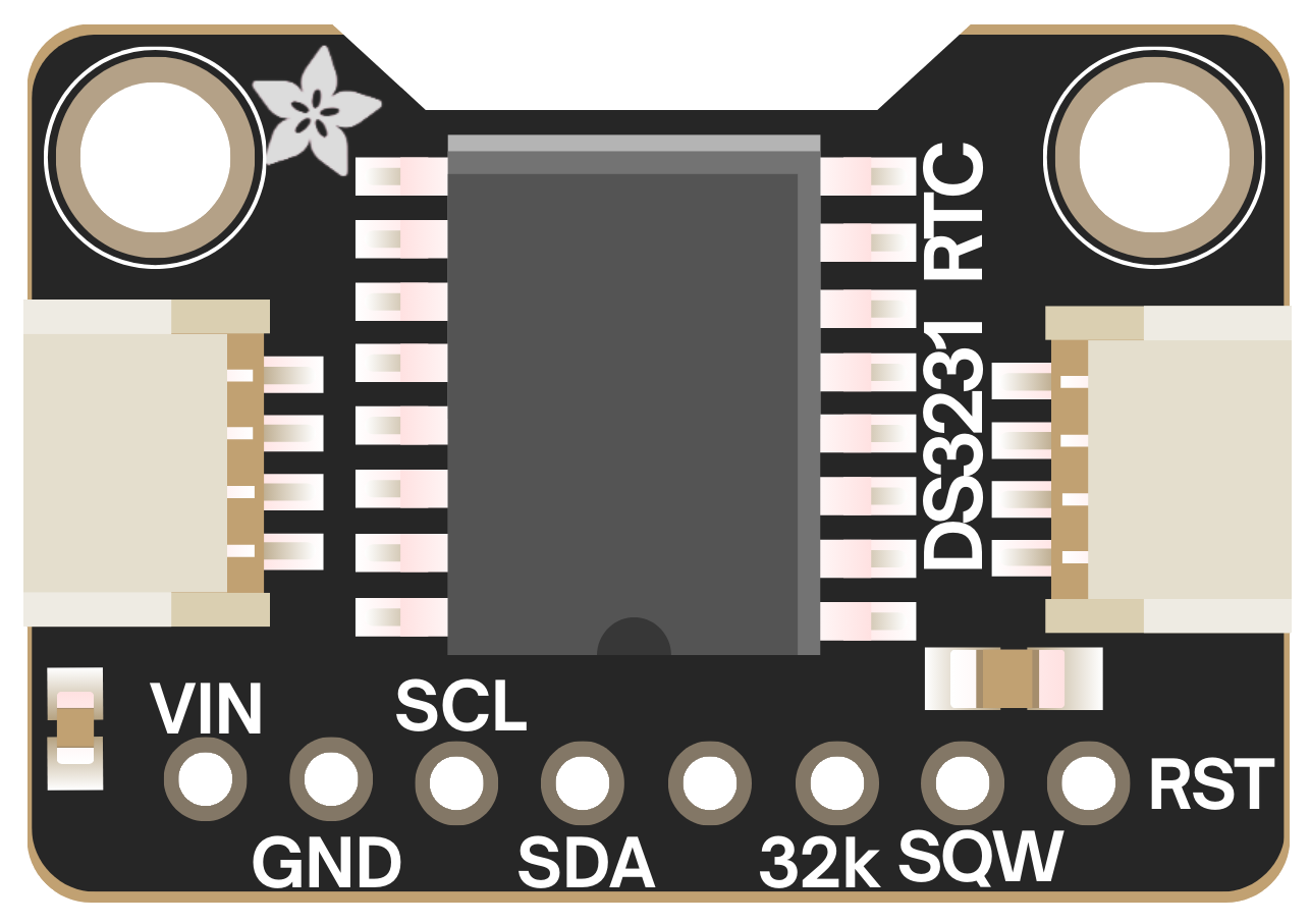
Pin Configuration
The DS3231 RTC Breakout features a Qwiic connector for I2C communication and additional breakout pins for flexibility. The pin configuration is as follows:
| Pin | Label | Description |
|---|---|---|
| 1 | GND | Ground (0V reference) |
| 2 | VCC | Power supply (3.3V to 5.5V) |
| 3 | SDA | I2C data line |
| 4 | SCL | I2C clock line |
| 5 | SQW | Square wave output (optional use) |
| 6 | 32K | 32.768 kHz output (optional use) |
Usage Instructions
Connecting the DS3231 RTC Breakout
- Power the Module: Connect the
VCCpin to a 3.3V or 5V power source and theGNDpin to ground. - I2C Communication: Use the Qwiic connector or connect the
SDAandSCLpins to the corresponding I2C pins on your microcontroller. - Optional Outputs: If needed, connect the
SQWor32Kpins to your circuit for additional functionality.
Using the DS3231 with an Arduino UNO
The DS3231 RTC Breakout is compatible with Arduino boards. Below is an example of how to use the module to read and display the current time and date.
Required Libraries
Install the following libraries in the Arduino IDE:
- Adafruit RTClib: Provides functions for interfacing with the DS3231.
Example Code
#include <Wire.h>
#include "RTClib.h"

// Create an RTC_DS3231 object to interact with the DS3231 module
RTC_DS3231 rtc;

void setup() {
  Serial.begin(9600); // Initialize serial communication for debugging
  Wire.begin();       // Initialize I2C communication

  // Check if the RTC is connected and working
  if (!rtc.begin()) {
    Serial.println("Couldn't find RTC. Check connections!");
    while (1); // Halt execution if RTC is not found
  }

  // Check if the RTC lost power and set the time if necessary
  if (rtc.lostPower()) {
    Serial.println("RTC lost power, setting the time!");
    // Set the RTC to the current date and time
    rtc.adjust(DateTime(F(__DATE__), F(__TIME__)));
  }
}

void loop() {
  // Get the current date and time from the RTC
  DateTime now = rtc.now();

  // Print the date and time to the Serial Monitor
  Serial.print(now.year(), DEC);
  Serial.print('/');
  Serial.print(now.month(), DEC);
  Serial.print('/');
  Serial.print(now.day(), DEC);
  Serial.print(" ");
  Serial.print(now.hour(), DEC);
  Serial.print(':');
  Serial.print(now.minute(), DEC);
  Serial.print(':');
  Serial.print(now.second(), DEC);
  Serial.println();

  delay(1000); // Wait for 1 second before updating
}
Best Practices
- Use a CR1220 coin cell battery to maintain timekeeping when the main power supply is disconnected.
- Avoid exposing the module to extreme temperatures beyond its operating range.
- Ensure proper pull-up resistors are present on the I2C lines if not already included in your setup.
Troubleshooting and FAQs
Common Issues
RTC Not Detected
- Cause: Incorrect wiring or I2C address mismatch.
- Solution: Verify the connections to the
SDAandSCLpins. Ensure the I2C address (default: 0x68) matches the one in your code.
Incorrect Time or Date
- Cause: RTC lost power or was not initialized properly.
- Solution: Check the backup battery and ensure the
rtc.adjust()function is called to set the correct time.
No Output on Serial Monitor
- Cause: Serial communication not initialized or incorrect baud rate.
- Solution: Ensure
Serial.begin(9600)is called in thesetup()function and the Serial Monitor is set to 9600 baud.
FAQs
Q: Can I use the DS3231 with a 3.3V microcontroller?
A: Yes, the DS3231 is compatible with both 3.3V and 5V systems.
Q: How long does the backup battery last?
A: A CR1220 coin cell can typically power the RTC for several years, depending on usage and environmental conditions.
Q: Can I use multiple DS3231 modules on the same I2C bus?
A: No, the DS3231 has a fixed I2C address (0x68). To use multiple modules, you would need an I2C multiplexer.
Q: What is the purpose of the SQW pin?
A: The SQW pin outputs a square wave signal, which can be configured for various frequencies (e.g., 1Hz, 4kHz) for timing or clocking purposes.