How to Use gear motor: Examples, Pinouts, and Specs
Introduction
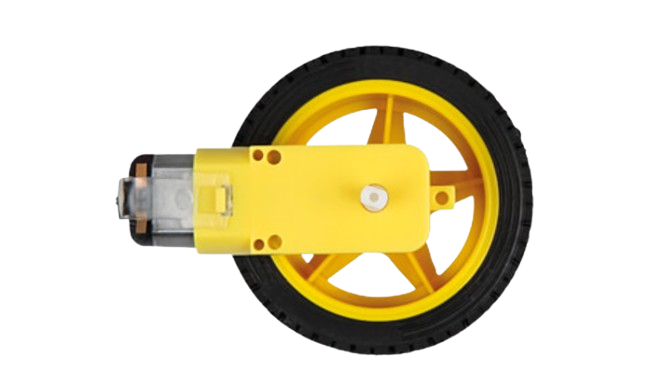
A gear motor, manufactured by Rajesh Shah (Part ID: Gear Motor), is an electric motor integrated with a gear system. This combination allows the motor to deliver high torque at low speeds, making it ideal for applications where precise control and power are required. Gear motors are widely used in robotics, conveyor systems, industrial machinery, and automotive applications.
Explore Projects Built with gear motor


Explore Projects Built with gear motor
Common Applications:
- Robotics: For driving wheels or robotic arms with controlled speed and torque.
- Conveyor Systems: To move materials at a consistent speed.
- Industrial Machinery: For applications requiring high torque at low RPM.
- Automotive: Used in power seats, windshield wipers, and other systems.
- Home Automation: In devices like motorized blinds or smart locks.
Technical Specifications
Below are the key technical details for the Rajesh Shah Gear Motor:
| Parameter | Value |
|---|---|
| Operating Voltage | 6V to 12V DC |
| Rated Torque | 5 kg·cm to 20 kg·cm |
| No-Load Speed | 30 RPM to 300 RPM (varies by model) |
| Gear Ratio | 10:1 to 100:1 (varies by model) |
| Current Consumption | 100 mA (no load) to 1.5 A (full load) |
| Shaft Diameter | 6 mm |
| Motor Type | Brushed DC Motor |
| Operating Temperature | -10°C to 50°C |
| Weight | 200 g to 500 g (varies by model) |
Pin Configuration and Descriptions
The gear motor typically has two terminals for electrical connections:
| Pin | Description |
|---|---|
| + | Positive terminal for power input (connect to Vcc) |
| - | Negative terminal for power input (connect to GND) |
Usage Instructions
How to Use the Gear Motor in a Circuit
- Power Supply: Connect the positive terminal of the gear motor to the power source (Vcc) and the negative terminal to ground (GND). Ensure the voltage matches the motor's operating range (6V to 12V DC).
- Motor Driver: Use a motor driver (e.g., L298N or L293D) to control the motor's speed and direction. Directly connecting the motor to a microcontroller is not recommended due to high current requirements.
- PWM Control: To control the speed, use Pulse Width Modulation (PWM) signals from a microcontroller like Arduino.
- Direction Control: Reverse the polarity of the motor terminals to change the direction of rotation.
Important Considerations and Best Practices
- Current Limiting: Ensure the power supply can handle the motor's peak current to avoid damage.
- Heat Dissipation: Prolonged operation at high torque may cause the motor to heat up. Allow for proper ventilation or cooling.
- Load Matching: Avoid overloading the motor beyond its rated torque to prevent gear or motor damage.
- Mounting: Securely mount the motor to prevent vibrations or misalignment during operation.
Example: Connecting a Gear Motor to Arduino UNO
Below is an example of controlling a gear motor using an Arduino UNO and an L298N motor driver:
// Example: Controlling a gear motor with Arduino UNO and L298N motor driver

// Define motor control pins
const int motorPin1 = 9; // IN1 on L298N
const int motorPin2 = 10; // IN2 on L298N
const int enablePin = 11; // ENA on L298N (PWM pin)

void setup() {
  // Set motor control pins as outputs
  pinMode(motorPin1, OUTPUT);
  pinMode(motorPin2, OUTPUT);
  pinMode(enablePin, OUTPUT);
}

void loop() {
  // Rotate motor in one direction
  digitalWrite(motorPin1, HIGH); // Set IN1 high
  digitalWrite(motorPin2, LOW);  // Set IN2 low
  analogWrite(enablePin, 128);   // Set speed (0-255)

  delay(2000); // Run for 2 seconds

  // Stop the motor
  digitalWrite(motorPin1, LOW);
  digitalWrite(motorPin2, LOW);
  delay(1000); // Pause for 1 second

  // Rotate motor in the opposite direction
  digitalWrite(motorPin1, LOW);  // Set IN1 low
  digitalWrite(motorPin2, HIGH); // Set IN2 high
  analogWrite(enablePin, 128);   // Set speed (0-255)

  delay(2000); // Run for 2 seconds

  // Stop the motor
  digitalWrite(motorPin1, LOW);
  digitalWrite(motorPin2, LOW);
  delay(1000); // Pause for 1 second
}
Troubleshooting and FAQs
Common Issues and Solutions
Motor Does Not Spin:
- Check the power supply voltage and current. Ensure it meets the motor's requirements.
- Verify the connections to the motor driver and ensure the control signals are correct.
Motor Spins in the Wrong Direction:
- Reverse the polarity of the motor terminals or adjust the control signals in the code.
Motor Overheats:
- Reduce the load on the motor or provide better cooling.
- Ensure the motor is not running continuously at its maximum torque.
Noisy Operation:
- Check for loose mounting or misaligned gears.
- Lubricate the gears if necessary.
PWM Control Not Working:
- Ensure the PWM pin is correctly configured in the code.
- Verify the motor driver supports PWM input.
FAQs
Q: Can I connect the gear motor directly to an Arduino?
A: No, the Arduino cannot supply the required current for the motor. Use a motor driver like L298N or L293D.
Q: How do I select the right gear motor for my application?
A: Consider the required torque, speed, and operating voltage. Match these parameters to the motor's specifications.
Q: Can the gear motor run in both directions?
A: Yes, by reversing the polarity of the motor terminals or using a motor driver to control the direction.
Q: What is the lifespan of the gear motor?
A: The lifespan depends on usage conditions, such as load, operating temperature, and maintenance. Proper care can extend its life significantly.