
How to Use LASSEN_IQ_GPS: Examples, Pinouts, and Specs
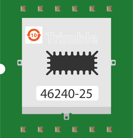
 Design with LASSEN_IQ_GPS in Cirkit Designer
Introduction
The LASSEN IQ GPS (Manufacturer Part ID: 46240-25) is a high-performance GPS receiver module developed by Trimble. It is designed to deliver precise positioning and navigation capabilities while maintaining low power consumption. With its compact size and fast time-to-first-fix (TTFF), the LASSEN IQ GPS is ideal for portable, embedded, and battery-powered applications. It supports multiple GPS signals, ensuring reliable performance in a wide range of environments.
Explore Projects Built with LASSEN_IQ_GPS
 Open Project in Cirkit Designer
 Open Project in Cirkit Designer
 Open Project in Cirkit Designer
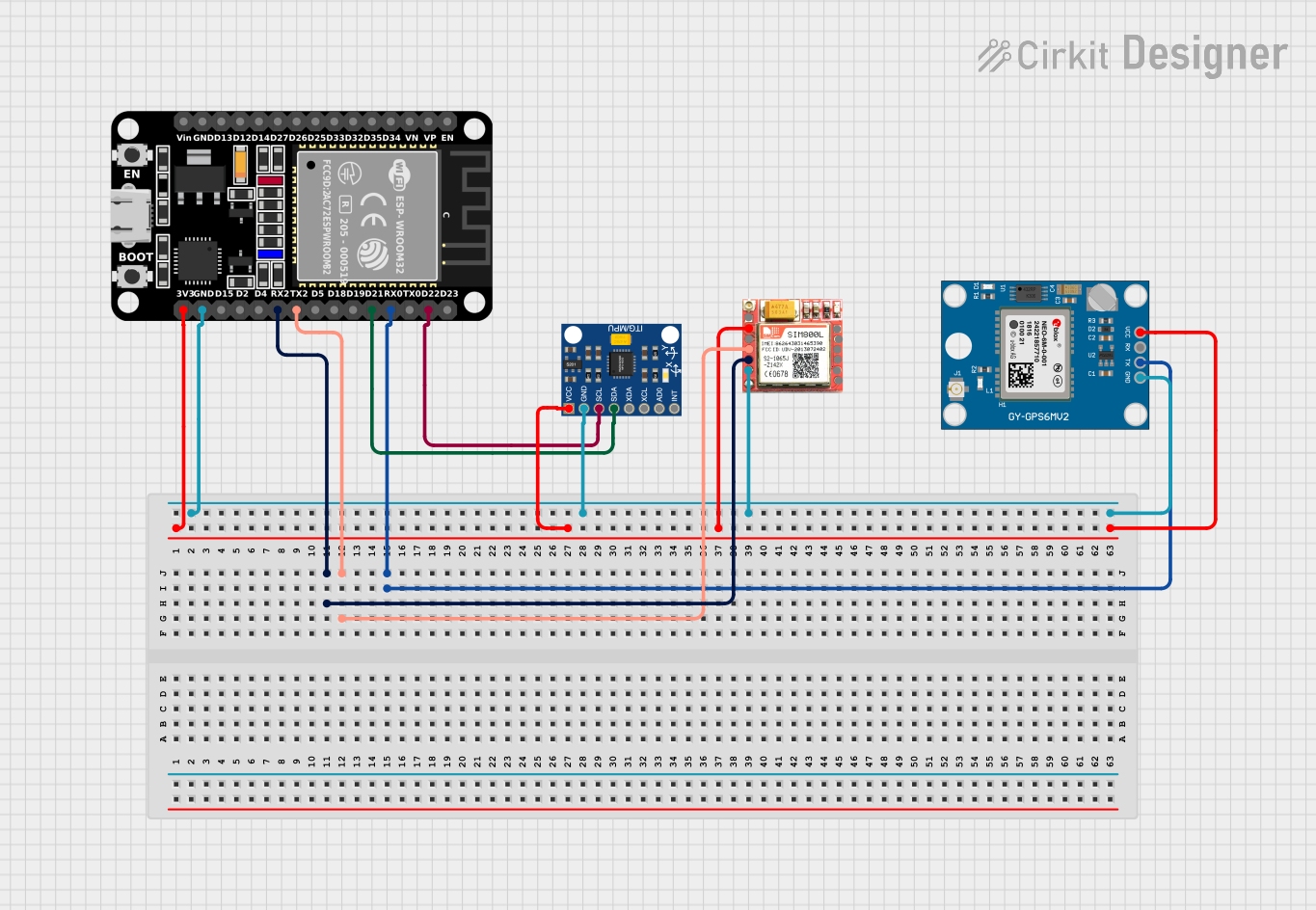 Open Project in Cirkit Designer
Explore Projects Built with LASSEN_IQ_GPS
Open Project in Cirkit DesignerOpen Project in Cirkit DesignerOpen Project in Cirkit DesignerOpen Project in Cirkit DesignerCommon Applications
- Portable navigation devices
- Asset tracking systems
- Unmanned aerial vehicles (UAVs)
- IoT devices requiring location services
- Automotive navigation systems
Technical Specifications
Key Technical Details
| Parameter | Specification |
|---|---|
| Manufacturer | Trimble |
| Part ID | 46240-25 |
| GPS Signals Supported | L1 C/A |
| Channels | 12 parallel channels |
| Time-to-First-Fix (TTFF) | < 1 second (hot start) |
| Position Accuracy | < 2.5 meters CEP |
| Velocity Accuracy | < 0.1 m/s |
| Update Rate | 1 Hz |
| Input Voltage | 3.3 V DC |
| Power Consumption | < 75 mW |
| Operating Temperature | -40°C to +85°C |
| Dimensions | 26 mm x 26 mm x 6 mm |
| Communication Interface | UART (TTL level) |
Pin Configuration and Descriptions
The LASSEN IQ GPS module has a 20-pin interface. Below is the pinout and description:
| Pin Number | Pin Name | Description |
|---|---|---|
| 1 | VCC | Power supply input (3.3 V DC) |
| 2 | GND | Ground |
| 3 | TXD | UART Transmit Data (TTL level) |
| 4 | RXD | UART Receive Data (TTL level) |
| 5 | PPS | Pulse Per Second output for timing applications |
| 6 | RESET_N | Active-low reset input |
| 7 | BOOT_SEL | Boot mode selection |
| 8 | ANT_PWR | External antenna power supply |
| 9 | ANT_DET | External antenna detection |
| 10 | RF_IN | GPS RF signal input |
| 11-20 | Reserved | Reserved for future use |
Usage Instructions
How to Use the LASSEN IQ GPS in a Circuit
- Power Supply: Connect the VCC pin to a regulated 3.3 V DC power source and the GND pin to the ground.
- UART Communication: Use the TXD and RXD pins to interface with a microcontroller or PC for data communication. Ensure the UART voltage levels are compatible (TTL level).
- Antenna Connection: Connect an active GPS antenna to the RF_IN pin. If using an external antenna, provide power through the ANT_PWR pin and monitor the ANT_DET pin for antenna status.
- Pulse Per Second (PPS): Use the PPS pin for precise timing applications if required.
- Reset: To reset the module, pull the RESET_N pin low momentarily.
Important Considerations
- Antenna Placement: Ensure the GPS antenna has a clear view of the sky for optimal signal reception.
- Power Supply: Use a stable and noise-free 3.3 V power source to avoid performance degradation.
- UART Configuration: Set the UART baud rate to 9600 bps (default) or configure it as per your application requirements.
- Startup Time: Allow the module a few seconds to acquire satellite signals during a cold start.
Example: Connecting to an Arduino UNO
Below is an example of how to interface the LASSEN IQ GPS with an Arduino UNO for basic GPS data reading:
Circuit Connections
| LASSEN IQ GPS Pin | Arduino UNO Pin |
|---|---|
| VCC | 3.3V |
| GND | GND |
| TXD | RX (Pin 0) |
| RXD | TX (Pin 1) |
Arduino Code
#include <SoftwareSerial.h>

// Define GPS module pins
SoftwareSerial gpsSerial(10, 11); // RX = Pin 10, TX = Pin 11

void setup() {
  Serial.begin(9600); // Initialize Serial Monitor
  gpsSerial.begin(9600); // Initialize GPS module communication

  Serial.println("LASSEN IQ GPS Module Test");
}

void loop() {
  // Check if data is available from the GPS module
  while (gpsSerial.available()) {
    char c = gpsSerial.read(); // Read one character from GPS
    Serial.print(c); // Print the character to Serial Monitor
  }
}
Note: Use a logic level shifter if interfacing the 3.3 V GPS module with the 5 V Arduino UNO.
Troubleshooting and FAQs
Common Issues and Solutions
No GPS Fix:
- Ensure the antenna has a clear view of the sky.
- Verify the antenna connection and power supply.
- Check for RF interference from nearby devices.
No Data Output:
- Confirm the UART connections (TXD and RXD).
- Verify the baud rate settings (default: 9600 bps).
- Ensure the module is powered correctly.
Inconsistent Position Data:
- Check the power supply for voltage fluctuations.
- Ensure the antenna is properly positioned and secured.
Module Not Responding:
- Perform a hardware reset by pulling the RESET_N pin low.
- Verify all connections and ensure no pins are left floating.
FAQs
Q1: Can the LASSEN IQ GPS work indoors?
A1: The module is designed for outdoor use with a clear view of the sky. Indoor performance may be limited due to signal attenuation.
Q2: What type of antenna is recommended?
A2: A high-gain active GPS antenna is recommended for optimal performance.
Q3: Can I change the default baud rate?
A3: Yes, the baud rate can be configured via specific NMEA commands. Refer to the manufacturer's documentation for details.
Q4: Is the module compatible with 5 V systems?
A4: The module operates at 3.3 V. Use a level shifter to interface with 5 V systems like Arduino UNO.
This concludes the documentation for the LASSEN IQ GPS module. For further details, refer to the official datasheet provided by Trimble.