
How to Use gps3: Examples, Pinouts, and Specs
 Design with gps3 in Cirkit Designer
Introduction
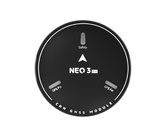
The GPS3 is a compact Global Positioning System module manufactured by GPS. It is designed to provide accurate location data and precise time information. With its small form factor and reliable performance, the GPS3 is widely used in navigation systems, asset tracking devices, and various IoT applications. Its versatility and ease of integration make it a popular choice for both hobbyists and professional developers.
Explore Projects Built with gps3
 Open Project in Cirkit Designer
 Open Project in Cirkit Designer
 Open Project in Cirkit Designer
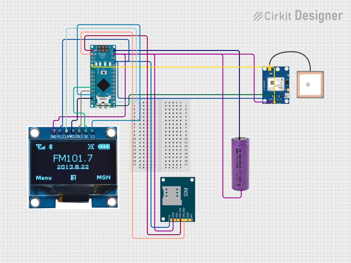 Open Project in Cirkit Designer
Explore Projects Built with gps3
Open Project in Cirkit DesignerOpen Project in Cirkit DesignerOpen Project in Cirkit DesignerOpen Project in Cirkit DesignerCommon Applications
- Vehicle navigation systems
- Personal tracking devices
- IoT-based location services
- Drones and robotics
- Time synchronization for networks and systems
Technical Specifications
The GPS3 module is engineered to deliver high performance while maintaining low power consumption. Below are its key technical specifications:
| Parameter | Value |
|---|---|
| Operating Voltage | 3.3V to 5.0V |
| Operating Current | 20mA (typical) |
| Communication Protocol | UART (default), I2C (optional) |
| Baud Rate (UART) | 9600 bps (default) |
| Position Accuracy | ±2.5 meters |
| Time Accuracy | ±30 nanoseconds |
| Update Rate | 1 Hz (configurable up to 10 Hz) |
| Operating Temperature | -40°C to +85°C |
| Dimensions | 25mm x 25mm x 6mm |
Pin Configuration
The GPS3 module has a simple pinout for easy integration into various systems. Below is the pin configuration:
| Pin | Name | Description |
|---|---|---|
| 1 | VCC | Power supply input (3.3V to 5.0V) |
| 2 | GND | Ground |
| 3 | TX | UART Transmit (data output from GPS3) |
| 4 | RX | UART Receive (data input to GPS3) |
| 5 | PPS | Pulse Per Second output for precise timing |
| 6 | EN | Enable pin (active high, used to power on/off module) |
Usage Instructions
Connecting the GPS3 Module
To use the GPS3 module in a circuit, follow these steps:
- Power Supply: Connect the VCC pin to a 3.3V or 5.0V power source and the GND pin to ground.
- UART Communication: Connect the TX pin of the GPS3 to the RX pin of your microcontroller (e.g., Arduino UNO) and the RX pin of the GPS3 to the TX pin of the microcontroller.
- Optional PPS Pin: If precise timing is required, connect the PPS pin to an interrupt-capable pin on your microcontroller.
- Enable Pin: Ensure the EN pin is pulled high to activate the module.
Important Considerations
- Use a decoupling capacitor (e.g., 10µF) near the VCC pin to stabilize the power supply.
- Place the GPS3 module in an open area with a clear view of the sky for optimal satellite reception.
- Avoid placing the module near high-frequency noise sources or metal enclosures that may interfere with GPS signals.
Example: Using GPS3 with Arduino UNO
Below is an example code snippet to interface the GPS3 module with an Arduino UNO:
#include <SoftwareSerial.h>

// Define GPS3 module pins
#define RX_PIN 4  // GPS3 TX pin connected to Arduino pin 4
#define TX_PIN 3  // GPS3 RX pin connected to Arduino pin 3

// Create a SoftwareSerial object for GPS communication
SoftwareSerial gpsSerial(RX_PIN, TX_PIN);

void setup() {
  Serial.begin(9600);         // Initialize Serial Monitor
  gpsSerial.begin(9600);      // Initialize GPS3 communication at 9600 bps
  Serial.println("GPS3 Module Initialized");
}

void loop() {
  // Check if data is available from the GPS3 module
  while (gpsSerial.available()) {
    char c = gpsSerial.read();  // Read one character from GPS3
    Serial.print(c);            // Print the character to Serial Monitor
  }
}
Notes:
- Ensure the GPS3 module is powered on and has a clear view of the sky.
- The default baud rate for the GPS3 module is 9600 bps. Adjust the
gpsSerial.begin()value if the baud rate is changed.
Troubleshooting and FAQs
Common Issues
No GPS Data Received
- Ensure the GPS3 module is powered on and properly connected.
- Verify that the TX and RX pins are correctly connected to the microcontroller.
- Check for a clear view of the sky to ensure satellite reception.
Inaccurate Location Data
- Allow the GPS3 module a few minutes to acquire satellite signals after powering on.
- Avoid using the module indoors or near tall buildings that may block GPS signals.
Module Not Responding
- Confirm that the EN pin is pulled high to enable the module.
- Check the power supply voltage and ensure it is within the specified range (3.3V to 5.0V).
FAQs
Q: Can the GPS3 module be used indoors?
A: While the GPS3 module may work indoors, its performance will be significantly reduced due to limited satellite visibility. For best results, use the module outdoors or near a window.
Q: How can I increase the update rate of the GPS3 module?
A: The update rate can be configured up to 10 Hz using specific commands sent via UART. Refer to the manufacturer's datasheet for detailed instructions.
Q: What is the purpose of the PPS pin?
A: The PPS (Pulse Per Second) pin provides a precise timing signal that can be used for time synchronization in applications requiring high accuracy.
Q: Can I use the GPS3 module with a 3.3V microcontroller?
A: Yes, the GPS3 module is compatible with both 3.3V and 5.0V systems. Ensure the power supply voltage matches the microcontroller's logic level.
By following this documentation, users can effectively integrate and utilize the GPS3 module in their projects.