Cirkit Designer Logo
Cirkit Designer
Your all-in-one circuit design IDE
Home / 
Component Documentation

How to Use KY-020: Examples, Pinouts, and Specs

Image of KY-020
Cirkit Designer LogoDesign with KY-020 in Cirkit Designer

Introduction

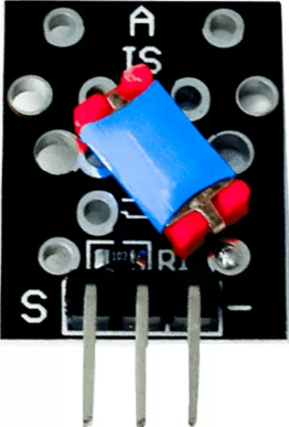
The KY-020 is a simple analog joystick module designed for two-dimensional control. Manufactured by Arduino, this module features two potentiometers that detect the position of the joystick along the X and Y axes. The output is provided as variable voltage signals, which can be easily read by microcontrollers such as the Arduino UNO. Additionally, the module includes a push-button switch that activates when the joystick is pressed down.

Explore Projects Built with KY-020

Use Cirkit Designer to design, explore, and prototype these projects online. Some projects support real-time simulation. Click "Open Project" to start designing instantly!
Arduino UNO Controlled RGB LED Light Show with Sound Detection
Image of Voice Sensor with RGB: A project utilizing KY-020 in a practical application
This circuit features an Arduino UNO microcontroller connected to a KY-038 sound sensor module and an RGB LED with individual resistors on each color channel. The Arduino is programmed to sequentially turn on the red, green, and blue channels of the RGB LED, each for a duration of 2 seconds. The sound sensor is powered by the Arduino and its analog and digital outputs are connected to the Arduino's analog and digital pins, respectively, for sound detection and processing.
Cirkit Designer LogoOpen Project in Cirkit Designer
ESP32-Based Security System with RFID and Laser Tripwire
Image of CPE doorlock system: A project utilizing KY-020 in a practical application
This circuit is designed for a comprehensive security and access control system with motion detection, access via RFID, and a break-beam sensor. It includes a solenoid lock controlled by a relay, visual and audible alerts, and a robust power management system with solar and battery backup to ensure uninterrupted operation.
Cirkit Designer LogoOpen Project in Cirkit Designer
Arduino Nano Joystick-Controlled Bluetooth Module with Battery Power
Image of padelpro transmitter: A project utilizing KY-020 in a practical application
This circuit is a wireless joystick controller that uses an Arduino Nano to read analog signals from a KY-023 Dual Axis Joystick Module and transmits the data via an HC-05 Bluetooth Module. The system is powered by a 18650 Li-Ion battery with a rocker switch for power control.
Cirkit Designer LogoOpen Project in Cirkit Designer
Arduino UNO Controlled Joystick Interface with LCD Feedback and Audio Alert
Image of 우주게임: A project utilizing KY-020 in a practical application
This circuit features an Arduino UNO microcontroller connected to a KY-023 Dual Axis Joystick Module, an I2C LCD 16x2 Screen, a Piezo Speaker, and a Pushbutton. The joystick provides two analog inputs to the Arduino for X and Y axis control, while the pushbutton is connected to a digital input for user interaction. The LCD screen displays information via I2C communication, and the Piezo Speaker is driven by a digital output from the Arduino for audio feedback.
Cirkit Designer LogoOpen Project in Cirkit Designer

Explore Projects Built with KY-020

Use Cirkit Designer to design, explore, and prototype these projects online. Some projects support real-time simulation. Click "Open Project" to start designing instantly!
Image of Voice Sensor with RGB: A project utilizing KY-020 in a practical application
Arduino UNO Controlled RGB LED Light Show with Sound Detection
This circuit features an Arduino UNO microcontroller connected to a KY-038 sound sensor module and an RGB LED with individual resistors on each color channel. The Arduino is programmed to sequentially turn on the red, green, and blue channels of the RGB LED, each for a duration of 2 seconds. The sound sensor is powered by the Arduino and its analog and digital outputs are connected to the Arduino's analog and digital pins, respectively, for sound detection and processing.
Cirkit Designer LogoOpen Project in Cirkit Designer
Image of CPE doorlock system: A project utilizing KY-020 in a practical application
ESP32-Based Security System with RFID and Laser Tripwire
This circuit is designed for a comprehensive security and access control system with motion detection, access via RFID, and a break-beam sensor. It includes a solenoid lock controlled by a relay, visual and audible alerts, and a robust power management system with solar and battery backup to ensure uninterrupted operation.
Cirkit Designer LogoOpen Project in Cirkit Designer
Image of padelpro transmitter: A project utilizing KY-020 in a practical application
Arduino Nano Joystick-Controlled Bluetooth Module with Battery Power
This circuit is a wireless joystick controller that uses an Arduino Nano to read analog signals from a KY-023 Dual Axis Joystick Module and transmits the data via an HC-05 Bluetooth Module. The system is powered by a 18650 Li-Ion battery with a rocker switch for power control.
Cirkit Designer LogoOpen Project in Cirkit Designer
Image of 우주게임: A project utilizing KY-020 in a practical application
Arduino UNO Controlled Joystick Interface with LCD Feedback and Audio Alert
This circuit features an Arduino UNO microcontroller connected to a KY-023 Dual Axis Joystick Module, an I2C LCD 16x2 Screen, a Piezo Speaker, and a Pushbutton. The joystick provides two analog inputs to the Arduino for X and Y axis control, while the pushbutton is connected to a digital input for user interaction. The LCD screen displays information via I2C communication, and the Piezo Speaker is driven by a digital output from the Arduino for audio feedback.
Cirkit Designer LogoOpen Project in Cirkit Designer

Common Applications and Use Cases

  • Robotics: Control of robotic arms, vehicles, or drones.
  • Gaming: Used as an input device for custom game controllers.
  • User Interfaces: Navigation in graphical user interfaces.
  • Educational Projects: Ideal for learning about analog input and microcontroller interfacing.

Technical Specifications

The KY-020 joystick module has the following key specifications:

Parameter Value
Manufacturer Arduino
Part ID KY-020
Operating Voltage 3.3V - 5V
Output Type Analog (X and Y axes), Digital (SW)
X-Axis Resistance 10 kΩ
Y-Axis Resistance 10 kΩ
Push-Button Type Normally Open (NO)
Dimensions 34mm x 26mm x 32mm

Pin Configuration and Descriptions

The KY-020 module has 5 pins, as described in the table below:

Pin Name Description
1 GND Ground connection for the module.
2 +5V Power supply input (3.3V to 5V).
3 VRx Analog output for the X-axis position.
4 VRy Analog output for the Y-axis position.
5 SW Digital output for the push-button (LOW when pressed, HIGH when released).

Usage Instructions

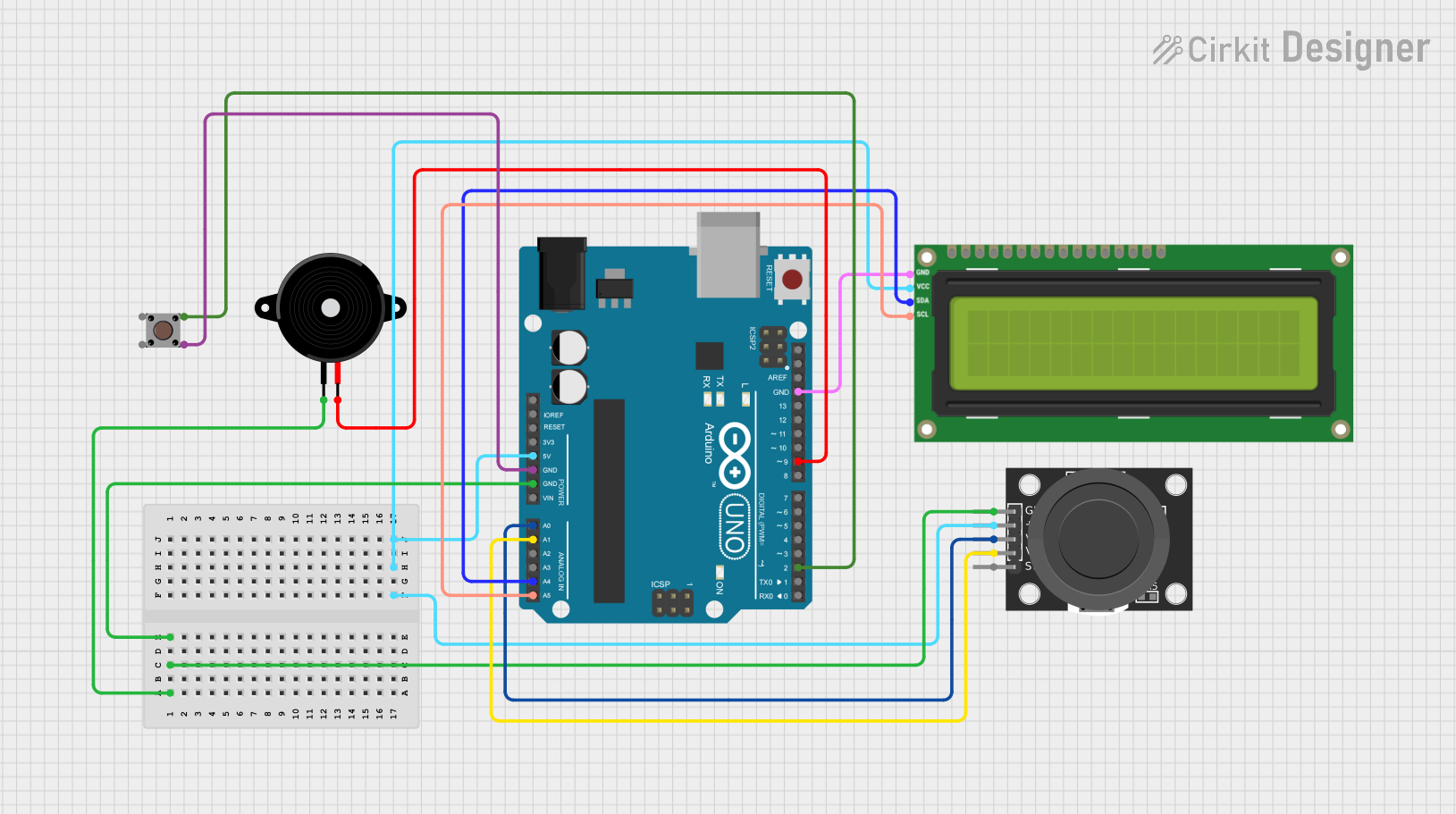
How to Use the KY-020 in a Circuit

  1. Power the Module: Connect the +5V pin to the 5V output of your microcontroller and the GND pin to ground.
  2. Read the X and Y Axes: Connect the VRx and VRy pins to analog input pins on your microcontroller to read the joystick's position.
  3. Monitor the Push-Button: Connect the SW pin to a digital input pin to detect when the joystick is pressed.
  4. Pull-Up Resistor for SW: If the microcontroller does not have an internal pull-up resistor, connect an external pull-up resistor (e.g., 10 kΩ) between the SW pin and +5V.

Important Considerations and Best Practices

  • Debouncing the Push-Button: Use software or hardware debouncing to ensure reliable detection of the button press.
  • Voltage Compatibility: Ensure the module's operating voltage matches your microcontroller's input voltage range.
  • Calibration: The joystick's analog outputs may vary slightly due to manufacturing tolerances. Calibrate the readings in your software for precise control.

Example Code for Arduino UNO

Below is an example Arduino sketch to read the joystick's X and Y positions and detect button presses:

// Define pin connections
const int VRxPin = A0; // X-axis analog output connected to A0
const int VRyPin = A1; // Y-axis analog output connected to A1
const int SWPin = 2;   // Push-button digital output connected to D2

void setup() {
  // Initialize serial communication for debugging
  Serial.begin(9600);

  // Configure the SW pin as input with an internal pull-up resistor
  pinMode(SWPin, INPUT_PULLUP);
}

void loop() {
  // Read the X and Y axis values (0 to 1023)
  int xValue = analogRead(VRxPin);
  int yValue = analogRead(VRyPin);

  // Read the state of the push-button (LOW when pressed)
  bool buttonPressed = !digitalRead(SWPin);

  // Print the joystick values to the Serial Monitor
  Serial.print("X: ");
  Serial.print(xValue);
  Serial.print(" | Y: ");
  Serial.print(yValue);
  Serial.print(" | Button: ");
  Serial.println(buttonPressed ? "Pressed" : "Released");

  // Add a small delay for stability
  delay(100);
}

Troubleshooting and FAQs

Common Issues and Solutions

  1. No Output from the Module

    • Cause: Incorrect wiring or insufficient power supply.
    • Solution: Double-check the connections and ensure the module is powered with 3.3V to 5V.
  2. Inconsistent Analog Readings

    • Cause: Electrical noise or poor connections.
    • Solution: Use shorter wires and ensure secure connections. Add capacitors (e.g., 0.1 µF) near the power pins to filter noise.
  3. Push-Button Not Detected

    • Cause: Missing pull-up resistor.
    • Solution: Enable the internal pull-up resistor in your microcontroller or add an external pull-up resistor.
  4. Joystick Center Position Not Zero

    • Cause: Manufacturing tolerances.
    • Solution: Calibrate the joystick in your software to account for the offset.

FAQs

Q1: Can the KY-020 be used with 3.3V microcontrollers like the ESP32?
A1: Yes, the KY-020 operates at 3.3V to 5V, making it compatible with 3.3V microcontrollers.

Q2: How do I increase the precision of the joystick readings?
A2: Use the microcontroller's ADC with higher resolution (e.g., 12-bit ADC) if available, and implement software filtering.

Q3: Can I use the KY-020 for 3D control?
A3: No, the KY-020 only supports two-dimensional control (X and Y axes). For 3D control, consider a joystick with an additional Z-axis.