How to Use KXD10036 RF Transmitter: Examples, Pinouts, and Specs
Introduction
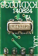
The KXD10036 RF Transmitter is a compact electronic device designed to transmit radio frequency signals wirelessly over a short distance. It is commonly used in remote control systems, wireless communication links, and various RF-enabled devices. The transmitter is known for its ease of use and integration into existing electronic projects, making it a popular choice for hobbyists and professionals alike.
Explore Projects Built with KXD10036 RF Transmitter

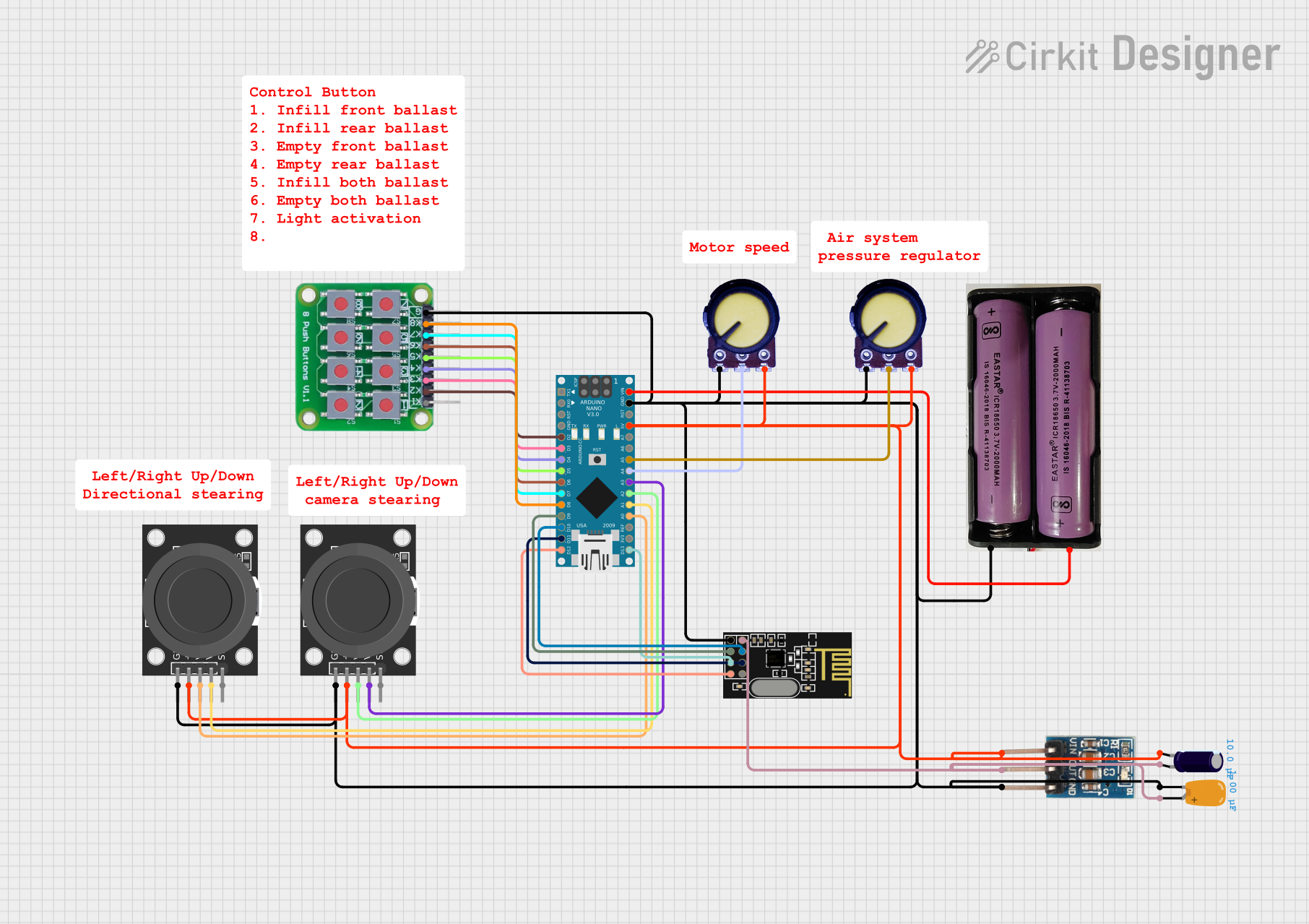


Explore Projects Built with KXD10036 RF Transmitter
Common Applications and Use Cases
- Remote control for consumer electronics (TVs, AC units)
- Wireless doorbells and security systems
- Radio-controlled toys
- Data transmission between embedded systems
- Telemetry and remote sensor data collection
Technical Specifications
Key Technical Details
- Operating Frequency: 433.92 MHz (common ISM band)
- Modulation: Amplitude Shift Keying (ASK)
- Supply Voltage: 3V to 12V DC
- Output Power: Up to 10mW (10dBm) at 12V
- Operating Current: 10mA (typical at 12V)
- Communication Range: Up to 100 meters (line-of-sight, antenna dependent)
Pin Configuration and Descriptions
| Pin Number | Name | Description |
|---|---|---|
| 1 | VCC | Power supply input (3V to 12V DC) |
| 2 | GND | Ground connection |
| 3 | DATA | Data input for modulation |
| 4 | ANT | Antenna connection (typically 17cm for 433MHz) |
Usage Instructions
How to Use the Component in a Circuit
- Connect the VCC pin to a DC power supply within the specified range (3V to 12V).
- Attach the GND pin to the common ground of your circuit.
- Interface the DATA pin with the output of your encoding or control circuit.
- Connect a suitable antenna to the ANT pin for signal transmission.
Important Considerations and Best Practices
- Ensure that the power supply does not exceed the maximum voltage rating to prevent damage.
- Use a quarter-wave monopole or a helical antenna for optimal range.
- Keep the antenna as straight as possible and away from metal objects.
- For better performance, match the antenna impedance with the transmitter.
- Avoid running the transmitter continuously at maximum power to prevent overheating.
- Shield the transmitter from noise sources to minimize interference.
Example Code for Arduino UNO
// Include the RadioHead Amplitude Shift Keying library
#include <RH_ASK.h>

// Create an instance of the ASK object
RH_ASK rf_transmitter;

void setup() {
  // Initialize ASK object with default settings
  if (!rf_transmitter.init()) {
    Serial.println("RF Transmitter init failed");
  }
}

void loop() {
  const char *msg = "Hello World";
  // Send a message wirelessly
  rf_transmitter.send((uint8_t *)msg, strlen(msg));
  rf_transmitter.waitPacketSent();
  // Wait for a second before sending the next message
  delay(1000);
}
Troubleshooting and FAQs
Common Issues Users Might Face
- No Signal Transmission: Ensure the antenna is properly connected and the power supply is within the specified range.
- Short Range: Check the antenna length and placement. Also, verify that the power supply voltage is adequate.
- Intermittent Transmission: This could be due to power supply instability or interference from other RF devices.
Solutions and Tips for Troubleshooting
- Double-check wiring and solder joints for any loose connections.
- Use a multimeter to verify the voltage at the VCC pin.
- Test the DATA input with an oscilloscope to ensure that the signal is being modulated correctly.
- If range is an issue, experiment with different antenna designs and orientations.
- Ensure that the transmitter is not placed near metal objects or electronic devices that could cause interference.
FAQs
Q: Can I use the KXD10036 RF Transmitter for long-distance communication? A: The KXD10036 is designed for short-range applications. For longer distances, consider using a more powerful transmitter or implementing a repeater.
Q: Is it legal to use the KXD10036 RF Transmitter? A: Yes, it operates in the 433.92 MHz ISM band, which is typically allowed for low-power devices, but always check local regulations.
Q: Can I connect multiple transmitters to create a network? A: Yes, but you will need to implement a protocol to manage the communication and avoid signal collision.
Q: What kind of data can I transmit with the KXD10036? A: You can transmit any digital data that can be modulated onto the carrier frequency, including binary, ASCII, or encoded sensor data.
Q: How can I increase the transmission range? A: Use a higher voltage within the allowed range, optimize the antenna design, and reduce obstacles between the transmitter and receiver.