How to Use KY-015: Examples, Pinouts, and Specs
Introduction
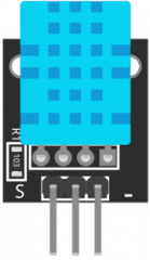
The KY-015 is a temperature and humidity sensor module that utilizes the DHT11 sensor. It is designed to provide accurate readings of ambient temperature and humidity levels, making it ideal for environmental monitoring applications. The module is widely used in weather stations, home automation systems, and agricultural monitoring setups. Its compact size and ease of use make it a popular choice for both hobbyists and professionals.
Explore Projects Built with KY-015

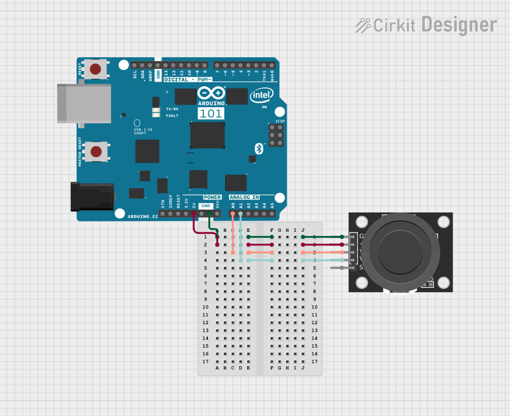
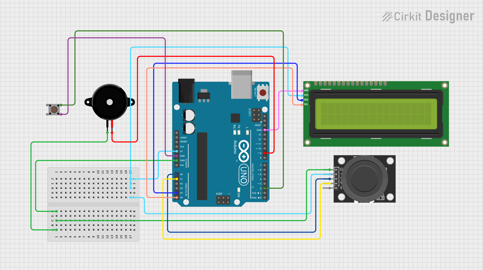

Explore Projects Built with KY-015
Common Applications
- Weather monitoring systems
- Home automation for climate control
- Greenhouse and agricultural monitoring
- IoT-based environmental sensing projects
- Educational projects for learning about sensors
Technical Specifications
The KY-015 module is built around the DHT11 sensor and has the following key specifications:
| Parameter | Value |
|---|---|
| Operating Voltage | 3.3V to 5.5V |
| Temperature Range | 0°C to 50°C |
| Temperature Accuracy | ±2°C |
| Humidity Range | 20% to 90% RH |
| Humidity Accuracy | ±5% RH |
| Communication Protocol | Digital (Single-Wire) |
| Dimensions | 28mm x 12mm x 10mm |
Pin Configuration
The KY-015 module has three pins for easy interfacing:
| Pin | Name | Description |
|---|---|---|
| 1 | VCC | Power supply pin (3.3V to 5.5V) |
| 2 | DATA | Digital data output pin for temperature and humidity |
| 3 | GND | Ground pin |
Usage Instructions
Connecting the KY-015 to a Circuit
- Power Supply: Connect the VCC pin to a 3.3V or 5V power source and the GND pin to the ground.
- Data Pin: Connect the DATA pin to a digital input pin on your microcontroller (e.g., Arduino UNO). A pull-up resistor (typically 10kΩ) is recommended between the DATA pin and VCC to ensure stable communication.
- Library: Use a compatible library (e.g., DHT library for Arduino) to simplify communication with the sensor.
Arduino UNO Example Code
Below is an example of how to use the KY-015 module with an Arduino UNO:
// Include the DHT library for communication with the KY-015 module
#include <DHT.h>

// Define the pin connected to the KY-015 DATA pin
#define DHTPIN 2

// Define the sensor type (DHT11 for KY-015)
#define DHTTYPE DHT11

// Initialize the DHT sensor
DHT dht(DHTPIN, DHTTYPE);

void setup() {
  // Start the serial communication for debugging
  Serial.begin(9600);
  Serial.println("KY-015 Temperature and Humidity Sensor Test");

  // Initialize the DHT sensor
  dht.begin();
}

void loop() {
  // Wait a few seconds between readings
  delay(2000);

  // Read temperature and humidity values
  float humidity = dht.readHumidity();
  float temperature = dht.readTemperature();

  // Check if the readings are valid
  if (isnan(humidity) || isnan(temperature)) {
    Serial.println("Failed to read from DHT sensor!");
    return;
  }

  // Print the readings to the serial monitor
  Serial.print("Humidity: ");
  Serial.print(humidity);
  Serial.print(" %\t");
  Serial.print("Temperature: ");
  Serial.print(temperature);
  Serial.println(" °C");
}
Important Considerations
- Pull-Up Resistor: Always use a pull-up resistor (10kΩ) on the DATA pin to ensure reliable communication.
- Sampling Rate: The DHT11 sensor has a sampling rate of 1Hz, meaning it can provide one reading per second. Avoid polling the sensor more frequently.
- Environmental Factors: Place the sensor in a location free from direct sunlight or water exposure to ensure accurate readings.
Troubleshooting and FAQs
Common Issues
No Data Output:
- Ensure the DATA pin is connected to the correct digital pin on the microcontroller.
- Verify that the pull-up resistor is properly connected between the DATA pin and VCC.
- Check the power supply voltage (3.3V to 5.5V).
Incorrect Readings:
- Ensure the sensor is not exposed to extreme environmental conditions outside its operating range.
- Verify that the sensor is not placed near heat sources or high humidity areas that could cause condensation.
"Failed to Read from DHT Sensor" Error:
- Ensure the DHT library is correctly installed in your Arduino IDE.
- Check the wiring and ensure all connections are secure.
FAQs
Q: Can the KY-015 module be used outdoors?
A: The KY-015 is not waterproof and should not be exposed to rain or direct sunlight. For outdoor use, consider placing it in a protective enclosure.
Q: What is the maximum cable length for the DATA pin?
A: The maximum cable length depends on the pull-up resistor value and environmental noise. For reliable communication, keep the cable length under 20 meters.
Q: Can I use the KY-015 with a 3.3V microcontroller?
A: Yes, the KY-015 is compatible with both 3.3V and 5V systems.
Q: How often can I read data from the KY-015?
A: The DHT11 sensor on the KY-015 module has a sampling rate of 1Hz, so you can read data once per second.