Cirkit Designer Logo
Cirkit Designer
Your all-in-one circuit design IDE
Home / 
Component Documentation

How to Use Gear Potentiometer: Examples, Pinouts, and Specs

Image of Gear Potentiometer
Cirkit Designer LogoDesign with Gear Potentiometer in Cirkit Designer

Introduction

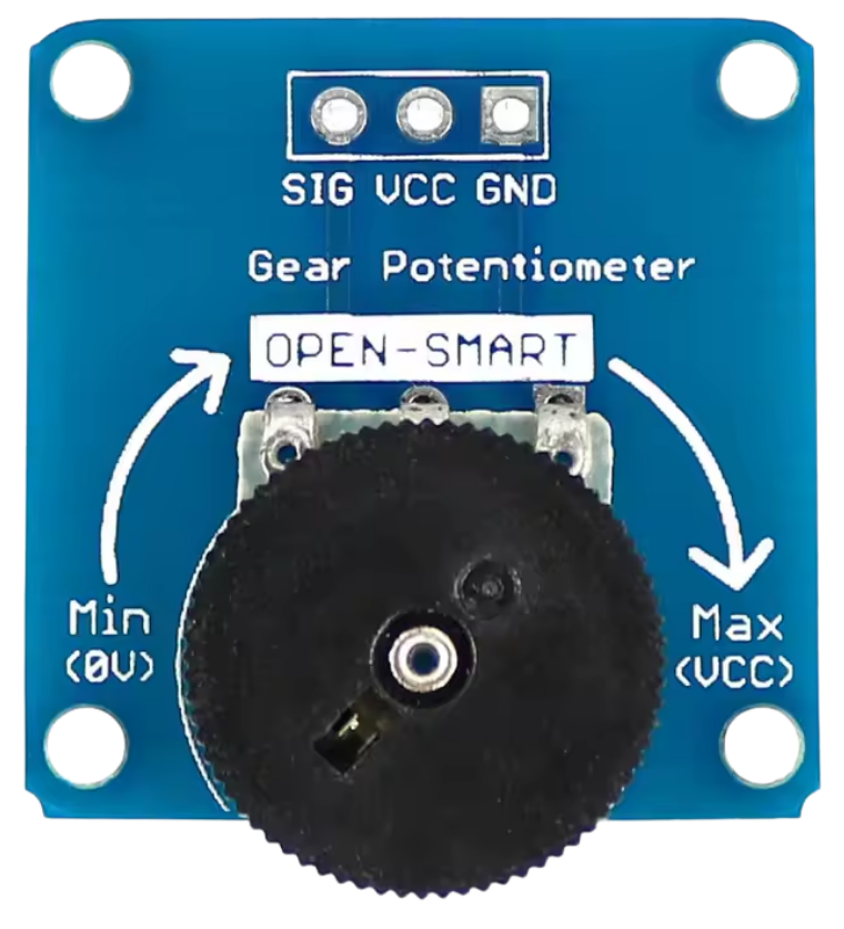
A gear potentiometer is a type of variable resistor that incorporates a gear mechanism to adjust its resistance. This design allows for precise and smooth control over electrical signals, making it ideal for applications where fine-tuning is essential. Gear potentiometers are commonly used in audio equipment for volume and tone control, robotics for position sensing, and industrial systems for feedback and calibration.

Explore Projects Built with Gear Potentiometer

Use Cirkit Designer to design, explore, and prototype these projects online. Some projects support real-time simulation. Click "Open Project" to start designing instantly!
Arduino Leonardo-Based Gaming Steering Wheel with Pedals and Gear Shifter
Image of DIY Steering Wheel: A project utilizing Gear Potentiometer in a practical application
This circuit is a gaming steering wheel system with 3 pedals and a gear shifter, interfaced with an Arduino Leonardo. It includes a 600 PPR optical rotary encoder for steering, three potentiometers for pedal input, and multiple push buttons connected via an IO expander for gear shifting and additional controls. The Arduino processes inputs from these components and communicates the data for further processing or display.
Cirkit Designer LogoOpen Project in Cirkit Designer
Variable Speed DC Motor Control with Rocker Switch
Image of motor speed control : A project utilizing Gear Potentiometer in a practical application
This circuit controls the speed of a DC motor using a potentiometer. The motor's power is supplied by a 9V battery, and a rocker switch is used to turn the motor on and off. The potentiometer adjusts the voltage applied to the motor, thereby controlling its speed.
Cirkit Designer LogoOpen Project in Cirkit Designer
Analog Multiplexer-Based Multi-Potentiometer Control System
Image of 172pot11mux: A project utilizing Gear Potentiometer in a practical application
This circuit consists of two 16-channel analog multiplexers, each connected to 16 rotary potentiometers. The potentiometers' wiper terminals are connected to the multiplexer channels, allowing the multiplexers to select and output the analog voltage from any of the potentiometers.
Cirkit Designer LogoOpen Project in Cirkit Designer
Teensy 4.1-Based Multi-Channel Potentiometer Interface with 74HC4051 Mux and AMS1117 3.3V Regulator
Image of redrum: A project utilizing Gear Potentiometer in a practical application
This circuit features a Teensy 4.1 microcontroller interfaced with a SparkFun 74HC4051 8-channel multiplexer to read multiple rotary potentiometers. The AMS1117 3.3V voltage regulator provides a stable 3.3V supply to the multiplexer and potentiometers, while electrolytic and ceramic capacitors are used for power supply filtering and stabilization.
Cirkit Designer LogoOpen Project in Cirkit Designer

Explore Projects Built with Gear Potentiometer

Use Cirkit Designer to design, explore, and prototype these projects online. Some projects support real-time simulation. Click "Open Project" to start designing instantly!
Image of DIY Steering Wheel: A project utilizing Gear Potentiometer in a practical application
Arduino Leonardo-Based Gaming Steering Wheel with Pedals and Gear Shifter
This circuit is a gaming steering wheel system with 3 pedals and a gear shifter, interfaced with an Arduino Leonardo. It includes a 600 PPR optical rotary encoder for steering, three potentiometers for pedal input, and multiple push buttons connected via an IO expander for gear shifting and additional controls. The Arduino processes inputs from these components and communicates the data for further processing or display.
Cirkit Designer LogoOpen Project in Cirkit Designer
Image of motor speed control : A project utilizing Gear Potentiometer in a practical application
Variable Speed DC Motor Control with Rocker Switch
This circuit controls the speed of a DC motor using a potentiometer. The motor's power is supplied by a 9V battery, and a rocker switch is used to turn the motor on and off. The potentiometer adjusts the voltage applied to the motor, thereby controlling its speed.
Cirkit Designer LogoOpen Project in Cirkit Designer
Image of 172pot11mux: A project utilizing Gear Potentiometer in a practical application
Analog Multiplexer-Based Multi-Potentiometer Control System
This circuit consists of two 16-channel analog multiplexers, each connected to 16 rotary potentiometers. The potentiometers' wiper terminals are connected to the multiplexer channels, allowing the multiplexers to select and output the analog voltage from any of the potentiometers.
Cirkit Designer LogoOpen Project in Cirkit Designer
Image of redrum: A project utilizing Gear Potentiometer in a practical application
Teensy 4.1-Based Multi-Channel Potentiometer Interface with 74HC4051 Mux and AMS1117 3.3V Regulator
This circuit features a Teensy 4.1 microcontroller interfaced with a SparkFun 74HC4051 8-channel multiplexer to read multiple rotary potentiometers. The AMS1117 3.3V voltage regulator provides a stable 3.3V supply to the multiplexer and potentiometers, while electrolytic and ceramic capacitors are used for power supply filtering and stabilization.
Cirkit Designer LogoOpen Project in Cirkit Designer

Technical Specifications

Below are the key technical details of a typical gear potentiometer:

  • Resistance Range: 1 kΩ to 100 kΩ (varies by model)
  • Tolerance: ±5% to ±10%
  • Power Rating: 0.25 W to 2 W
  • Maximum Voltage: 250 V DC
  • Rotation Angle: 270° to 360° (depending on the gear design)
  • Gear Ratio: Typically 1:4 or 1:6 for finer adjustments
  • Operating Temperature: -40°C to +85°C
  • Shaft Diameter: 6 mm (standard)
  • Lifespan: 10,000 to 50,000 cycles

Pin Configuration and Descriptions

The gear potentiometer typically has three pins, as described in the table below:

Pin Name Description
1 Terminal 1 One end of the resistive element. Connect to ground or a reference voltage.
2 Wiper (Output) The adjustable output that provides a variable resistance based on the gear's position.
3 Terminal 2 The other end of the resistive element. Connect to a power source or signal input.

Usage Instructions

How to Use the Component in a Circuit

  1. Basic Connection:

    • Connect Pin 1 to ground (GND).
    • Connect Pin 3 to the positive voltage supply (e.g., 5V or 3.3V).
    • Use Pin 2 (wiper) as the output to obtain a variable voltage or resistance.
  2. Adjusting Resistance:

    • Rotate the gear mechanism to change the position of the wiper along the resistive element.
    • The output voltage at the wiper (Pin 2) will vary proportionally to the rotation angle.
  3. Example Circuit:

    • Use the gear potentiometer as a voltage divider to control the brightness of an LED or as an input to a microcontroller for analog signal reading.

Important Considerations and Best Practices

  • Avoid Overloading: Ensure the power rating of the potentiometer is not exceeded to prevent damage.
  • Mechanical Stress: Do not apply excessive force to the gear mechanism to avoid wear or breakage.
  • Debouncing: If used in digital circuits, consider implementing software debouncing to handle noise from mechanical adjustments.
  • Mounting: Secure the potentiometer properly to prevent movement during operation, especially in robotics or industrial applications.

Arduino UNO Example Code

Below is an example of how to use a gear potentiometer with an Arduino UNO to read its analog output and control an LED's brightness:

// Define the pin connections
const int potPin = A0;  // Connect the wiper (Pin 2) to analog pin A0
const int ledPin = 9;   // Connect an LED to digital pin 9 (PWM-enabled)

void setup() {
  pinMode(ledPin, OUTPUT);  // Set the LED pin as an output
  Serial.begin(9600);       // Initialize serial communication for debugging
}

void loop() {
  int potValue = analogRead(potPin);  // Read the potentiometer value (0-1023)
  
  // Map the potentiometer value to a PWM range (0-255)
  int ledBrightness = map(potValue, 0, 1023, 0, 255);
  
  analogWrite(ledPin, ledBrightness);  // Set the LED brightness
  
  // Print the potentiometer value for debugging
  Serial.print("Potentiometer Value: ");
  Serial.println(potValue);
  
  delay(100);  // Small delay for stability
}

Troubleshooting and FAQs

Common Issues Users Might Face

  1. No Output Voltage:

    • Cause: Incorrect wiring or loose connections.
    • Solution: Verify that all pins are connected properly and securely.
  2. Inconsistent or Noisy Output:

    • Cause: Dust or wear on the resistive element.
    • Solution: Clean the potentiometer with contact cleaner or replace it if worn out.
  3. Gear Mechanism Stuck or Slipping:

    • Cause: Mechanical damage or debris in the gear system.
    • Solution: Inspect and clean the gear mechanism. Avoid applying excessive force.
  4. Overheating:

    • Cause: Exceeding the power rating.
    • Solution: Ensure the potentiometer is used within its specified power and voltage limits.

Solutions and Tips for Troubleshooting

  • Check Resistance: Use a multimeter to measure the resistance between Pins 1 and 3 to ensure it matches the specified range.
  • Test the Wiper: Measure the resistance between Pin 1 and Pin 2 while rotating the gear to confirm smooth variation.
  • Secure Mounting: Ensure the potentiometer is firmly mounted to avoid mechanical stress during operation.

By following this documentation, users can effectively integrate and troubleshoot a gear potentiometer in their projects.