Cirkit Designer Logo
Cirkit Designer
Your all-in-one circuit design IDE
Home / 
Component Documentation

How to Use QF-RD21H Time Delayed Relay: Examples, Pinouts, and Specs

Image of QF-RD21H Time Delayed Relay
Cirkit Designer LogoDesign with QF-RD21H Time Delayed Relay in Cirkit Designer

Introduction

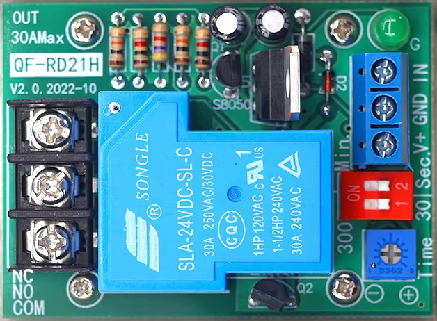
The QF-RD21H Time Delayed Relay is a versatile electronic component designed to activate after a preset delay, enabling precise timed control of electrical circuits. This relay is widely used in automation, industrial control systems, and home automation projects where timing functions are critical. Its ability to delay activation makes it ideal for applications such as motor control, lighting systems, and sequential circuit operations.

Explore Projects Built with QF-RD21H Time Delayed Relay

Use Cirkit Designer to design, explore, and prototype these projects online. Some projects support real-time simulation. Click "Open Project" to start designing instantly!
Arduino UNO Controlled Relay with DS3231 RTC
Image of Hooter connections: A project utilizing QF-RD21H Time Delayed Relay in a practical application
This circuit features an Arduino UNO microcontroller connected to a DS3231 Real Time Clock (RTC) module and a 12V single-channel relay. The Arduino provides power to both the RTC and the relay, and it communicates with the RTC via I2C using the SDA and SCL lines connected to A4 and A5 respectively. The relay is controlled by the Arduino through a digital output on pin D13, allowing the Arduino to switch external loads on and off based on time events managed by the RTC.
Cirkit Designer LogoOpen Project in Cirkit Designer
NFC-Enabled Access Control System with Real-Time Clock and OLED Display
Image of doorlock: A project utilizing QF-RD21H Time Delayed Relay in a practical application
This circuit is designed as an access control system with time-tracking capabilities. It uses an NFC/RFID reader for authentication, a real-time clock for time-stamping events, and an OLED display for user interface, all controlled by a T8_S3 microcontroller. A relay module actuates a magnetic lock, and a button switch provides additional user input, with a switching power supply delivering the necessary voltages.
Cirkit Designer LogoOpen Project in Cirkit Designer
Arduino Nano Controlled Timer with Relay, Buzzer, and I2C LCD Display
Image of Automatic solar light with timer: A project utilizing QF-RD21H Time Delayed Relay in a practical application
This circuit is designed as a configurable timer system controlled by an Arduino Nano, which drives a relay to switch a 240V bulb on and off. The timer duration can be adjusted using pushbuttons, and the remaining time is displayed on an I2C LCD screen. When the timer expires, a buzzer sounds, and the relay turns off the bulb, indicating the end of the timing period.
Cirkit Designer LogoOpen Project in Cirkit Designer
NFC-Enabled Access Control System with Time Logging
Image of doorlock: A project utilizing QF-RD21H Time Delayed Relay in a practical application
This circuit is designed for access control with time tracking capabilities. It features an NFC/RFID reader for authentication, an RTC module (DS3231) for real-time clock functionality, and an OLED display for user interaction. A 12V relay controls a magnetic lock, which is activated upon successful NFC/RFID authentication, and a button switch is likely used for manual operation or input. The T8_S3 microcontroller serves as the central processing unit, interfacing with the NFC/RFID reader, RTC, OLED, and relay to manage the access control logic.
Cirkit Designer LogoOpen Project in Cirkit Designer

Explore Projects Built with QF-RD21H Time Delayed Relay

Use Cirkit Designer to design, explore, and prototype these projects online. Some projects support real-time simulation. Click "Open Project" to start designing instantly!
Image of Hooter connections: A project utilizing QF-RD21H Time Delayed Relay in a practical application
Arduino UNO Controlled Relay with DS3231 RTC
This circuit features an Arduino UNO microcontroller connected to a DS3231 Real Time Clock (RTC) module and a 12V single-channel relay. The Arduino provides power to both the RTC and the relay, and it communicates with the RTC via I2C using the SDA and SCL lines connected to A4 and A5 respectively. The relay is controlled by the Arduino through a digital output on pin D13, allowing the Arduino to switch external loads on and off based on time events managed by the RTC.
Cirkit Designer LogoOpen Project in Cirkit Designer
Image of doorlock: A project utilizing QF-RD21H Time Delayed Relay in a practical application
NFC-Enabled Access Control System with Real-Time Clock and OLED Display
This circuit is designed as an access control system with time-tracking capabilities. It uses an NFC/RFID reader for authentication, a real-time clock for time-stamping events, and an OLED display for user interface, all controlled by a T8_S3 microcontroller. A relay module actuates a magnetic lock, and a button switch provides additional user input, with a switching power supply delivering the necessary voltages.
Cirkit Designer LogoOpen Project in Cirkit Designer
Image of Automatic solar light with timer: A project utilizing QF-RD21H Time Delayed Relay in a practical application
Arduino Nano Controlled Timer with Relay, Buzzer, and I2C LCD Display
This circuit is designed as a configurable timer system controlled by an Arduino Nano, which drives a relay to switch a 240V bulb on and off. The timer duration can be adjusted using pushbuttons, and the remaining time is displayed on an I2C LCD screen. When the timer expires, a buzzer sounds, and the relay turns off the bulb, indicating the end of the timing period.
Cirkit Designer LogoOpen Project in Cirkit Designer
Image of doorlock: A project utilizing QF-RD21H Time Delayed Relay in a practical application
NFC-Enabled Access Control System with Time Logging
This circuit is designed for access control with time tracking capabilities. It features an NFC/RFID reader for authentication, an RTC module (DS3231) for real-time clock functionality, and an OLED display for user interaction. A 12V relay controls a magnetic lock, which is activated upon successful NFC/RFID authentication, and a button switch is likely used for manual operation or input. The T8_S3 microcontroller serves as the central processing unit, interfacing with the NFC/RFID reader, RTC, OLED, and relay to manage the access control logic.
Cirkit Designer LogoOpen Project in Cirkit Designer

Technical Specifications

The QF-RD21H Time Delayed Relay is built to handle a variety of timing and load requirements. Below are its key technical details:

General Specifications

Parameter Value
Operating Voltage 12V DC / 24V DC / 110V AC / 220V AC (varies by model)
Contact Type SPDT (Single Pole Double Throw)
Contact Rating 10A @ 250V AC / 10A @ 30V DC
Timing Range 0.1 seconds to 10 minutes (adjustable)
Power Consumption < 1W
Operating Temperature -20°C to +60°C
Dimensions 70mm x 40mm x 25mm

Pin Configuration and Descriptions

The QF-RD21H relay typically has 5 pins for connection. Below is the pinout description:

Pin Number Label Description
1 VCC Positive power supply input
2 GND Ground connection
3 Trigger Input signal to start the delay timer
4 NO (Normally Open) Connect to the load; closes after delay
5 COM (Common) Common terminal for the relay contacts

Usage Instructions

How to Use the QF-RD21H in a Circuit

  1. Power Supply: Connect the VCC pin to the positive terminal of your power source and the GND pin to the negative terminal. Ensure the voltage matches the relay's operating voltage (e.g., 12V DC or 220V AC).
  2. Trigger Signal: Apply a trigger signal to the Trigger pin. This signal can be a high logic level (e.g., 5V for DC models) or a momentary pulse, depending on your application.
  3. Load Connection:
    • Connect one terminal of your load to the NO (Normally Open) pin.
    • Connect the other terminal of the load to the power source.
    • The COM (Common) pin serves as the shared connection for the relay contacts.
  4. Adjust Timing: Use the onboard potentiometer to set the desired delay time. Turn clockwise to increase the delay and counterclockwise to decrease it.

Important Considerations and Best Practices

  • Voltage Compatibility: Ensure the relay's operating voltage matches your circuit's power supply.
  • Load Ratings: Do not exceed the relay's contact rating (10A @ 250V AC or 10A @ 30V DC) to avoid damage.
  • Trigger Signal: Use a clean and stable trigger signal to ensure reliable operation.
  • Isolation: For high-voltage applications, ensure proper isolation between the relay and low-voltage control circuits.

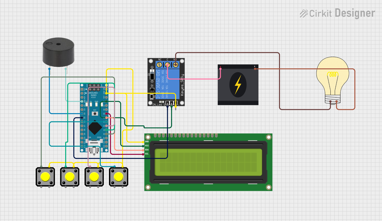
Example: Using the QF-RD21H with an Arduino UNO

The QF-RD21H can be easily integrated with an Arduino UNO for automated timing control. Below is an example code snippet:

// Example: Controlling the QF-RD21H Time Delayed Relay with Arduino UNO

const int relayTriggerPin = 7; // Pin connected to the Trigger pin of the relay
const int delayTime = 5000;    // Delay time in milliseconds (5 seconds)

void setup() {
  pinMode(relayTriggerPin, OUTPUT); // Set the relay trigger pin as an output
  digitalWrite(relayTriggerPin, LOW); // Ensure the relay is off initially
}

void loop() {
  digitalWrite(relayTriggerPin, HIGH); // Send a trigger signal to the relay
  delay(100); // Keep the trigger signal high for 100ms
  digitalWrite(relayTriggerPin, LOW); // Turn off the trigger signal

  delay(delayTime); // Wait for the delay time before repeating
}

Notes:

  • Connect the relay's Trigger pin to the Arduino's relayTriggerPin (e.g., pin 7).
  • Ensure the relay's power supply is separate from the Arduino's power supply if using a high-voltage model.

Troubleshooting and FAQs

Common Issues and Solutions

  1. Relay Does Not Activate:

    • Cause: Insufficient power supply or incorrect wiring.
    • Solution: Verify the power supply voltage and ensure all connections are secure.
  2. Relay Activates Immediately Without Delay:

    • Cause: Faulty trigger signal or incorrect timing adjustment.
    • Solution: Check the trigger signal for stability and adjust the potentiometer to set the desired delay.
  3. Load Does Not Operate:

    • Cause: Load exceeds the relay's contact rating or incorrect wiring.
    • Solution: Ensure the load is within the relay's rated capacity and verify the wiring.
  4. Relay Overheats:

    • Cause: Continuous operation at maximum load or poor ventilation.
    • Solution: Reduce the load or improve ventilation around the relay.

FAQs

  • Q: Can the QF-RD21H handle AC and DC loads?
    A: Yes, the relay can handle both AC and DC loads, provided they are within the rated voltage and current limits.

  • Q: How do I reset the delay timer?
    A: The delay timer resets automatically when the trigger signal is removed and reapplied.

  • Q: Can I use the relay for high-power devices like motors?
    A: Yes, but ensure the motor's starting current does not exceed the relay's contact rating.

By following this documentation, you can effectively integrate the QF-RD21H Time Delayed Relay into your projects for reliable and precise timing control.