
How to Use Pushbutton STOP: Examples, Pinouts, and Specs
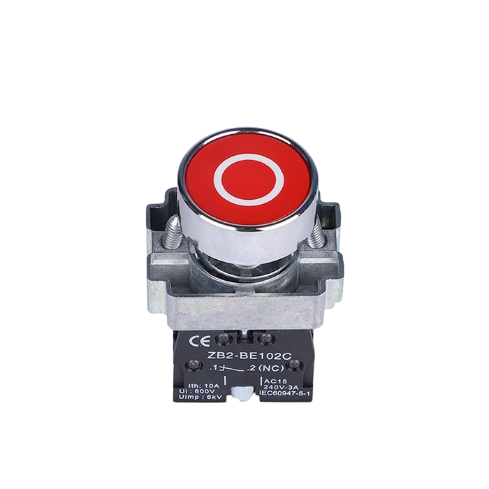
 Design with Pushbutton STOP in Cirkit Designer
Introduction
The Pushbutton STOP is a momentary switch designed to interrupt an electrical circuit when pressed. It is commonly used in safety-critical applications to stop machines, processes, or systems immediately. This component is an essential part of emergency stop mechanisms in industrial, commercial, and even DIY projects. Its simple operation and reliability make it a popular choice for controlling power flow in circuits.
Explore Projects Built with Pushbutton STOP
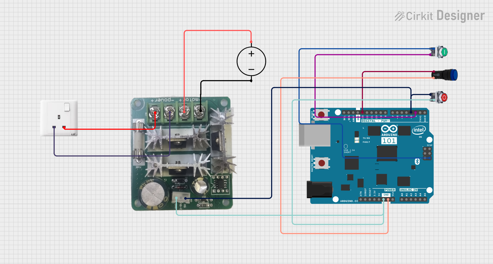 Open Project in Cirkit Designer
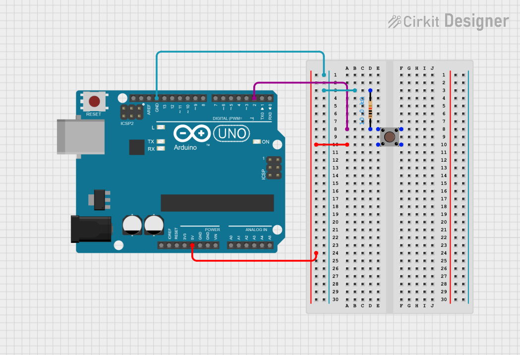 Open Project in Cirkit Designer
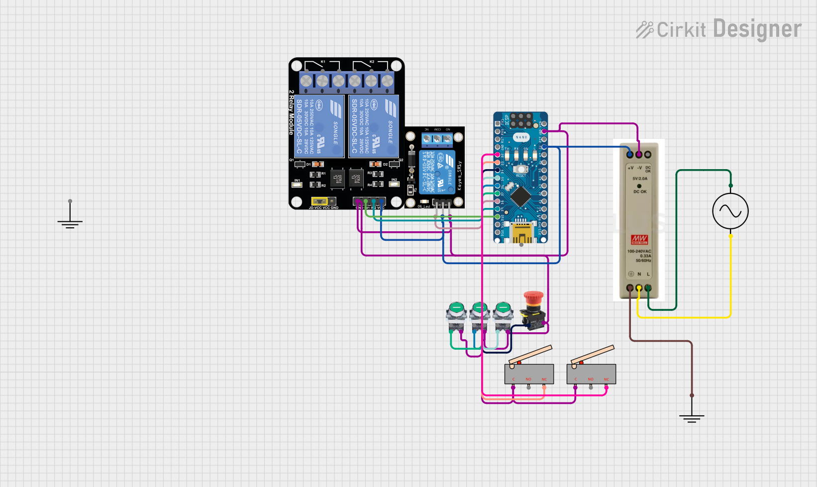 Open Project in Cirkit Designer
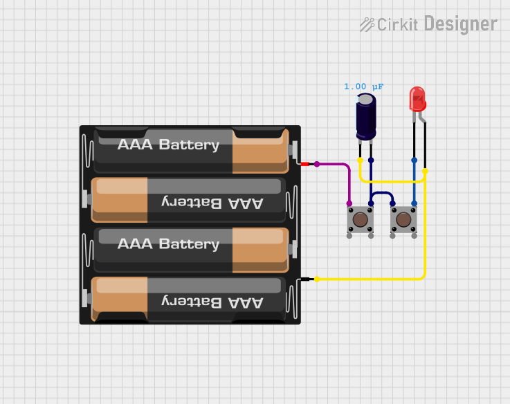 Open Project in Cirkit Designer
Explore Projects Built with Pushbutton STOP
Open Project in Cirkit DesignerOpen Project in Cirkit DesignerOpen Project in Cirkit DesignerOpen Project in Cirkit DesignerCommon Applications and Use Cases
- Emergency stop buttons in industrial machinery
- Safety mechanisms in automation systems
- DIY electronics projects requiring a manual stop function
- Power interruption in motor control circuits
- Reset or stop functionality in Arduino-based projects
Technical Specifications
The Pushbutton STOP is a normally open (NO) momentary switch, meaning it only interrupts the circuit while pressed. Below are its key technical details:
Key Specifications
| Parameter | Value |
|---|---|
| Operating Voltage | 3V to 250V (AC/DC) |
| Maximum Current Rating | 3A |
| Contact Resistance | ≤ 50 mΩ |
| Insulation Resistance | ≥ 100 MΩ |
| Mechanical Durability | ≥ 1,000,000 cycles |
| Operating Temperature | -25°C to +85°C |
| Mounting Style | Panel mount |
| Switch Type | Momentary, Normally Open (NO) |
Pin Configuration and Descriptions
The Pushbutton STOP typically has two terminals for connection:
| Pin Name | Description |
|---|---|
| Terminal 1 (Input) | Connects to the power source or signal input. |
| Terminal 2 (Output) | Connects to the load or circuit to be interrupted. |
Usage Instructions
How to Use the Pushbutton STOP in a Circuit
- Identify the Terminals: Locate the two terminals on the pushbutton. These are typically labeled or can be identified using a multimeter.
- Connect the Circuit:
- Connect one terminal to the power source or signal input.
- Connect the other terminal to the load or circuit that needs to be interrupted.
- Mount the Pushbutton: Secure the pushbutton in a panel or enclosure using the provided mounting hardware.
- Test the Circuit: Ensure the circuit operates as expected. Pressing the button should interrupt the circuit momentarily.
Important Considerations and Best Practices
- Voltage and Current Ratings: Ensure the operating voltage and current do not exceed the component's maximum ratings.
- Debouncing: When used in digital circuits, consider implementing a debouncing mechanism to avoid false triggering.
- Safety: For emergency stop applications, ensure the button is easily accessible and clearly labeled.
- Wiring: Use appropriate wire gauges and insulation for the operating current and voltage.
Example: Using Pushbutton STOP with Arduino UNO
The Pushbutton STOP can be used with an Arduino UNO to stop a process or reset a system. Below is an example circuit and code:
Circuit Setup
- Connect one terminal of the pushbutton to a digital input pin (e.g., pin 2) on the Arduino.
- Connect the other terminal to the ground (GND).
- Use a pull-up resistor (10kΩ) between the digital input pin and 5V to ensure a stable HIGH signal when the button is not pressed.
Arduino Code
// Define the pin connected to the Pushbutton STOP
const int buttonPin = 2; // Digital pin 2
const int ledPin = 13;   // Built-in LED for indication

void setup() {
  pinMode(buttonPin, INPUT_PULLUP); // Set button pin as input with pull-up resistor
  pinMode(ledPin, OUTPUT);         // Set LED pin as output
  digitalWrite(ledPin, HIGH);      // Turn on LED initially
}

void loop() {
  int buttonState = digitalRead(buttonPin); // Read the button state

  if (buttonState == LOW) { // Button pressed (LOW due to pull-up)
    digitalWrite(ledPin, LOW); // Turn off LED to simulate stopping a process
    delay(1000);              // Debounce delay
  } else {
    digitalWrite(ledPin, HIGH); // Keep LED on when button is not pressed
  }
}
Troubleshooting and FAQs
Common Issues
- Button Does Not Interrupt the Circuit:
- Check the wiring and ensure the terminals are connected correctly.
- Verify that the button is not damaged or worn out.
- False Triggers in Digital Circuits:
- Implement a hardware or software debounce mechanism to stabilize the signal.
- Button Feels Stuck or Unresponsive:
- Inspect for physical obstructions or dirt. Clean the button if necessary.
FAQs
Q: Can the Pushbutton STOP handle AC and DC circuits?
A: Yes, it is designed to handle both AC and DC circuits within its voltage and current ratings.
Q: How do I implement debouncing in software?
A: Use a small delay (e.g., 50ms) after detecting a button press to filter out noise or false triggers.
Q: Is the Pushbutton STOP waterproof?
A: Standard models are not waterproof. For outdoor or wet environments, use a waterproof version or install it in a sealed enclosure.
Q: Can I use this button to control high-power devices?
A: No, the button is rated for a maximum of 3A. Use a relay or contactor for high-power applications.