How to Use rn2483a breakout board: Examples, Pinouts, and Specs

Introduction
The RN2483A breakout board is a development tool designed to simplify the use of the RN2483A LoRaWAN module. This breakout board provides easy access to the module's pins, making it ideal for prototyping and development in Internet of Things (IoT) applications. The RN2483A module itself is a low-power, long-range LoRaWAN transceiver operating in the 868 MHz and 915 MHz ISM bands, enabling robust wireless communication over long distances.
Explore Projects Built with rn2483a breakout board

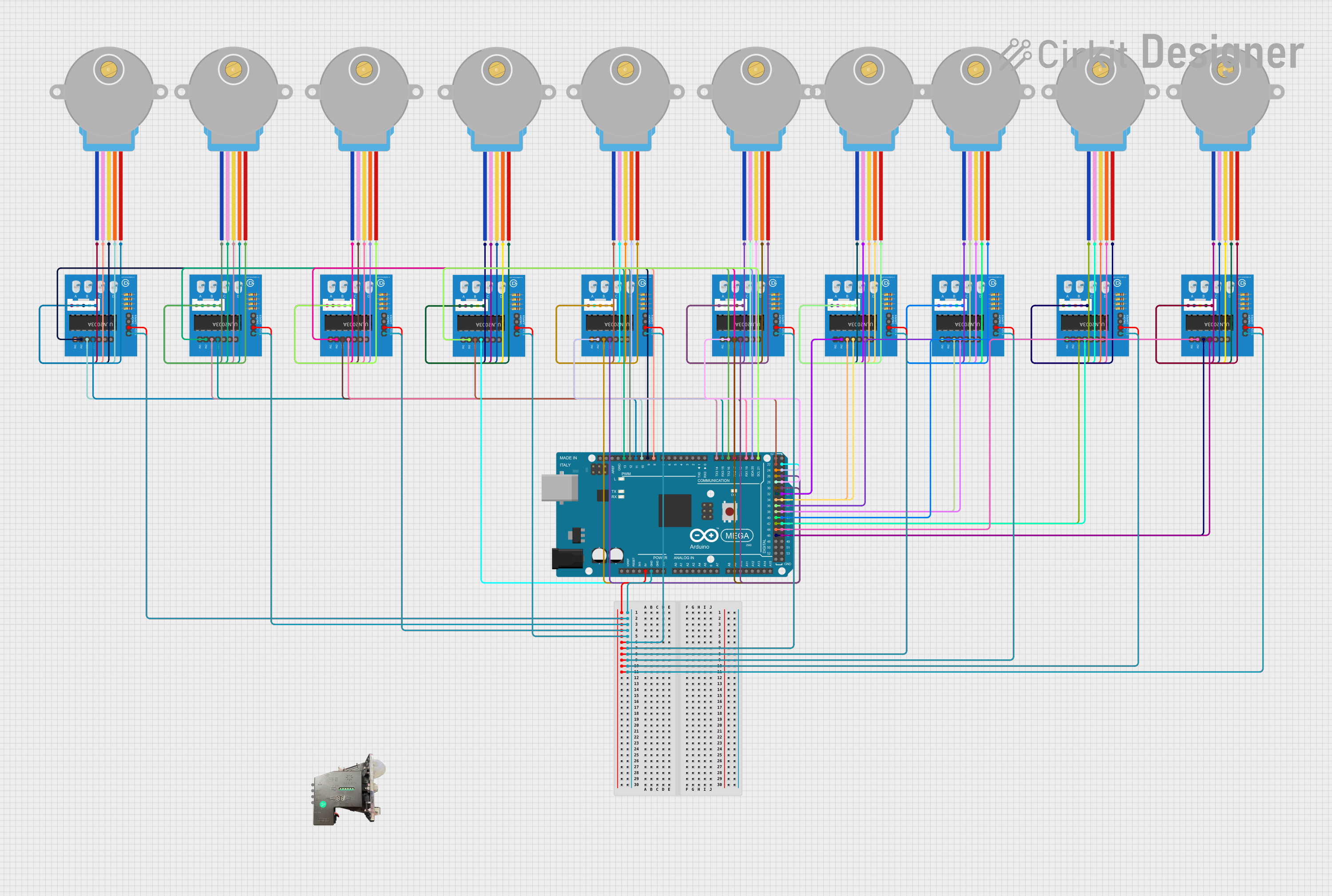
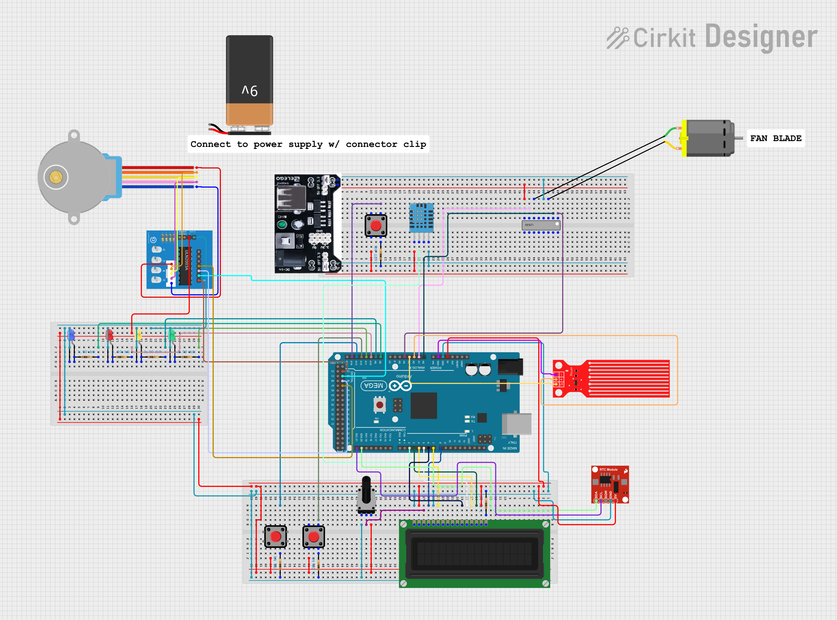
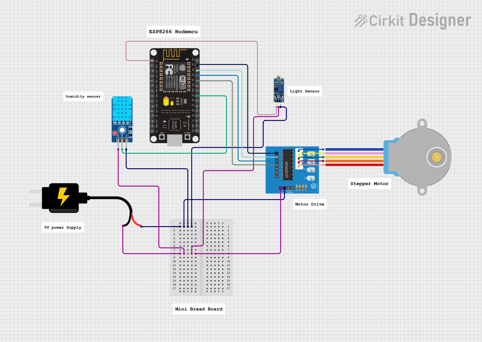
Explore Projects Built with rn2483a breakout board
Common Applications and Use Cases
- IoT sensor networks
- Smart agriculture and environmental monitoring
- Industrial automation and control
- Asset tracking and geolocation
- Smart cities and infrastructure monitoring
Technical Specifications
Key Technical Details
- Module: RN2483A LoRaWAN transceiver
- Frequency Bands: 868 MHz (EU) / 915 MHz (US)
- Communication Protocol: LoRaWAN Class A and Class C
- Supply Voltage: 2.1V to 3.6V (typically 3.3V)
- Current Consumption:
- Sleep mode: ~1.5 µA
- Transmit mode: ~38 mA (at +14 dBm)
- Output Power: Up to +14 dBm (default) or +20 dBm (boost mode)
- Interface: UART (3.3V logic level)
- Antenna Connector: U.FL or SMA (depending on breakout board design)
- Operating Temperature: -40°C to +85°C
Pin Configuration and Descriptions
The RN2483A breakout board exposes the following pins for easy access:
| Pin Name | Description | Direction | Notes |
|---|---|---|---|
| VCC | Power supply input (2.1V–3.6V) | Input | Typically connected to 3.3V |
| GND | Ground | - | Common ground for the circuit |
| TX | UART Transmit | Output | Connect to RX of microcontroller |
| RX | UART Receive | Input | Connect to TX of microcontroller |
| RESET | Module reset | Input | Active low, pull low to reset |
| ANTX | Antenna TX enable | Output | Controls external RF switch (if used) |
| GPIO0 | General-purpose I/O pin 0 | Input/Output | Configurable via firmware |
| GPIO1 | General-purpose I/O pin 1 | Input/Output | Configurable via firmware |
| GPIO2 | General-purpose I/O pin 2 | Input/Output | Configurable via firmware |
| GPIO3 | General-purpose I/O pin 3 | Input/Output | Configurable via firmware |
| RF_OUT | RF signal output | Output | Connect to antenna via U.FL/SMA |
Usage Instructions
How to Use the RN2483A Breakout Board in a Circuit
- Power Supply: Connect the VCC pin to a 3.3V power source and GND to the ground of your circuit.
- UART Communication: Connect the TX pin of the breakout board to the RX pin of your microcontroller, and the RX pin of the breakout board to the TX pin of your microcontroller.
- Antenna Connection: Attach an appropriate antenna to the RF_OUT pin or the U.FL/SMA connector for optimal signal transmission and reception.
- Reset: Optionally, connect the RESET pin to a GPIO pin on your microcontroller to allow software-controlled resets.
- GPIO Pins: Use the GPIO pins for additional functionality, such as controlling external devices or reading sensor inputs.
Important Considerations and Best Practices
- Voltage Levels: Ensure that the breakout board is powered with a voltage within the specified range (2.1V–3.6V). Exceeding this range may damage the module.
- Antenna Selection: Use an antenna tuned for the appropriate frequency band (868 MHz or 915 MHz) to ensure optimal performance.
- UART Configuration: Set the UART baud rate to 57600 bps (default) for communication with the RN2483A module.
- LoRaWAN Configuration: Configure the module with the appropriate LoRaWAN parameters (e.g., DevEUI, AppEUI, AppKey) before use.
- Firmware Updates: Check for firmware updates from the manufacturer to ensure compatibility with the latest LoRaWAN standards.
Example: Connecting to an Arduino UNO
Below is an example of how to connect the RN2483A breakout board to an Arduino UNO and send a basic LoRaWAN message.
Wiring Diagram
| RN2483A Pin | Arduino UNO Pin |
|---|---|
| VCC | 3.3V |
| GND | GND |
| TX | D2 (SoftwareSerial RX) |
| RX | D3 (SoftwareSerial TX) |
| RESET | D4 |
Arduino Code
#include <SoftwareSerial.h>

// Define SoftwareSerial pins for RN2483A communication
SoftwareSerial loraSerial(2, 3); // RX = D2, TX = D3

void setup() {
  // Initialize serial communication
  Serial.begin(9600); // For debugging
  loraSerial.begin(57600); // RN2483A default baud rate

  // Send initialization commands to RN2483A
  Serial.println("Initializing RN2483A...");
  loraSerial.println("sys reset"); // Reset the module
  delay(1000);

  // Join a LoRaWAN network (replace with your credentials)
  loraSerial.println("mac set devaddr 26011BDA"); // Example DevAddr
  loraSerial.println("mac set nwkskey 2B7E151628AED2A6ABF7158809CF4F3C"); // Example NwkSKey
  loraSerial.println("mac set appskey 2B7E151628AED2A6ABF7158809CF4F3C"); // Example AppSKey
  loraSerial.println("mac join abp"); // Join using ABP mode
  delay(2000);

  // Send a test message
  loraSerial.println("mac tx uncnf 1 48656C6C6F"); // Send "Hello" in hex
  delay(1000);
}

void loop() {
  // Continuously read responses from the RN2483A
  while (loraSerial.available()) {
    String response = loraSerial.readString();
    Serial.println(response); // Print response to Serial Monitor
  }
}
Troubleshooting and FAQs
Common Issues and Solutions
No Response from the Module:
- Ensure the module is powered correctly (3.3V on VCC and GND connected).
- Verify UART connections (TX to RX and RX to TX).
- Check the baud rate (default is 57600 bps).
LoRaWAN Join Fails:
- Verify that the DevEUI, AppEUI, and AppKey (or DevAddr, NwkSKey, and AppSKey for ABP) are correctly configured.
- Ensure the module is within range of a LoRaWAN gateway.
Poor Signal Quality:
- Check the antenna connection and ensure it is tuned for the correct frequency band.
- Avoid placing the module near sources of RF interference.
Module Resets Unexpectedly:
- Ensure the power supply is stable and within the specified voltage range.
- Avoid excessive current draw from GPIO pins.
FAQs
Can I use the RN2483A breakout board with 5V microcontrollers?
- No, the RN2483A operates at 3.3V logic levels. Use a level shifter if interfacing with 5V devices.
What is the maximum range of the RN2483A module?
- The range depends on environmental factors but can reach up to 15 km in rural areas and 2–5 km in urban areas.
How do I update the firmware on the RN2483A module?
- Firmware updates can be performed using the Microchip LoRa Development Utility via a USB-to-UART adapter.
This documentation provides a comprehensive guide to using the RN2483A breakout board for your IoT projects.