How to Use current to voltage convertor: Examples, Pinouts, and Specs
Introduction
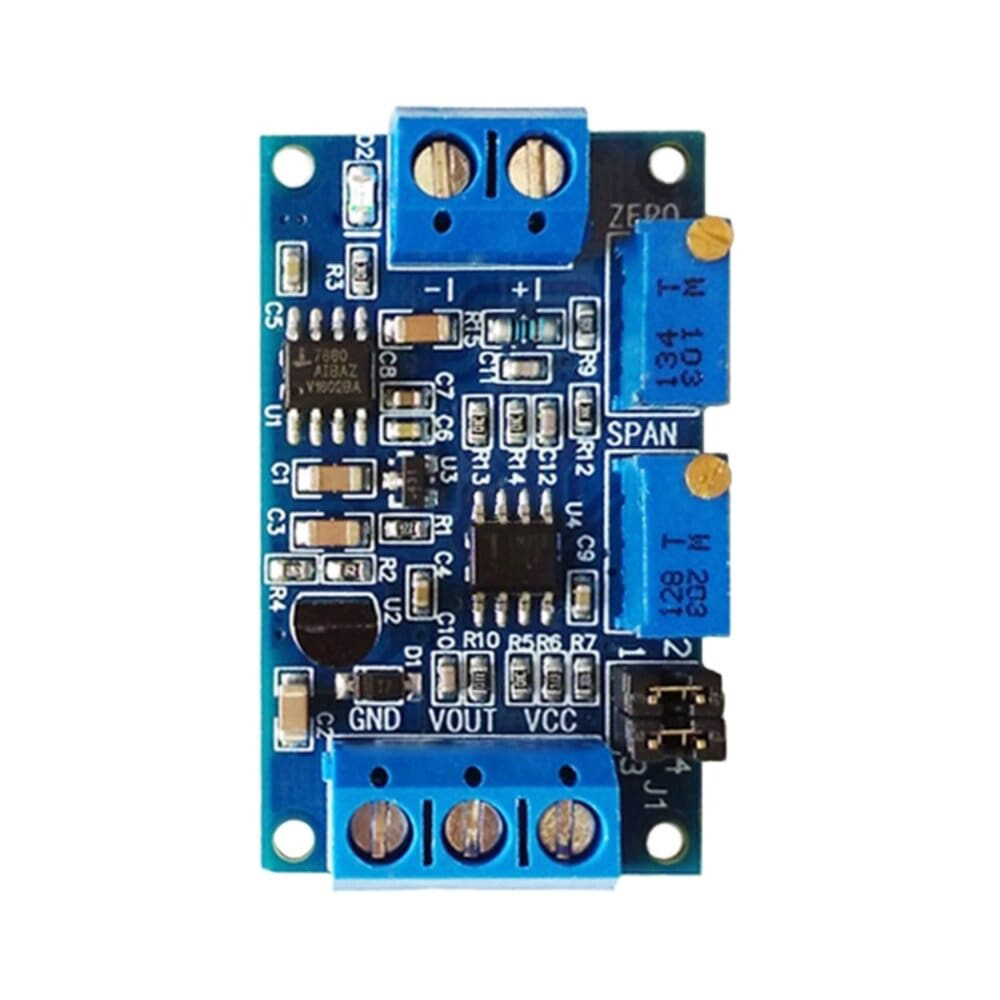
A current to voltage converter is an electronic device that converts an input current signal into a proportional output voltage signal. This component is widely used in measurement and control systems, where current signals from sensors or transducers need to be converted into voltage signals for further processing or interfacing with other devices. Its high precision and reliability make it an essential component in industrial automation, medical instrumentation, and data acquisition systems.
Explore Projects Built with current to voltage convertor


Explore Projects Built with current to voltage convertor
Technical Specifications
Below are the general technical specifications for a typical current to voltage converter. Specific values may vary depending on the model or manufacturer.
General Specifications
- Input Current Range: 0 µA to 20 mA (typical), or 4 mA to 20 mA for industrial standards
- Output Voltage Range: 0 V to 10 V (typical)
- Supply Voltage: ±15 V DC or 5 V DC (depending on the design)
- Conversion Accuracy: ±0.1% of full scale
- Input Impedance: Low (to ensure accurate current measurement)
- Output Impedance: Low (to drive subsequent stages effectively)
- Operating Temperature: -40°C to 85°C
Pin Configuration and Descriptions
The pin configuration of a current to voltage converter IC or module may vary. Below is an example of a typical 8-pin configuration:
| Pin Number | Pin Name | Description |
|---|---|---|
| 1 | V+ | Positive supply voltage input (e.g., +15 V or +5 V). |
| 2 | IN+ | Non-inverting input for the current signal. |
| 3 | IN- | Inverting input for the current signal. |
| 4 | GND | Ground connection. |
| 5 | OUT | Voltage output proportional to the input current. |
| 6 | NC | No connection (leave unconnected or refer to the datasheet for specific use). |
| 7 | OFFSET/TRIM | Offset adjustment or trimming pin (optional, for calibration). |
| 8 | V- | Negative supply voltage input (e.g., -15 V or ground for single-supply designs). |
Usage Instructions
How to Use the Component in a Circuit
- Power Supply: Connect the positive and negative supply voltage pins (V+ and V-) to the appropriate power source. Ensure the supply voltage matches the component's specifications.
- Input Signal: Connect the current signal source to the IN+ and IN- pins. For single-ended inputs, connect IN- to ground.
- Output Signal: The output voltage will appear at the OUT pin. Connect this pin to the next stage of your circuit, such as an ADC (Analog-to-Digital Converter) or a microcontroller.
- Offset Adjustment: If the component includes an offset adjustment pin, use a potentiometer or resistor network to calibrate the output voltage to zero when the input current is zero.
Important Considerations and Best Practices
- Input Impedance: Ensure the input impedance of the converter is low to avoid affecting the current signal source.
- Output Load: Avoid connecting a high-impedance load to the output, as it may distort the voltage signal.
- Decoupling Capacitors: Place decoupling capacitors (e.g., 0.1 µF and 10 µF) near the power supply pins to reduce noise and improve stability.
- Temperature Effects: Be aware of temperature variations, as they may affect the accuracy of the conversion. Use components with a low temperature coefficient for critical applications.
Example: Connecting to an Arduino UNO
Below is an example of how to interface a current to voltage converter with an Arduino UNO to read a 4-20 mA current signal and display the corresponding voltage.
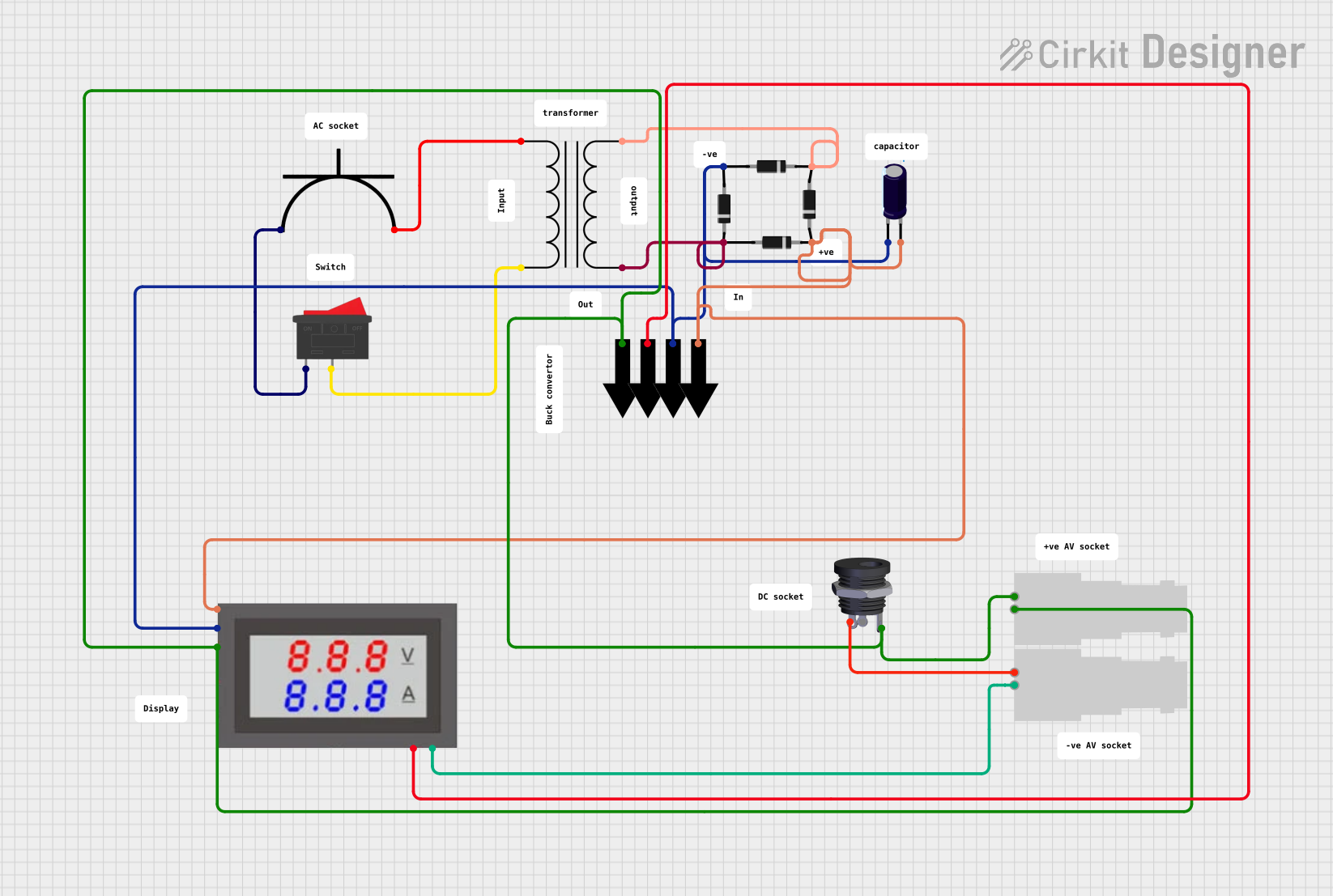
Circuit Diagram
- Connect the OUT pin of the converter to an analog input pin (e.g., A0) on the Arduino.
- Connect the GND pin of the converter to the Arduino's GND.
- Power the converter using a ±15 V supply or a single 5 V supply, depending on its specifications.
Arduino Code
// Define the analog input pin
const int analogPin = A0;

// Define the reference voltage of the Arduino (5V for most boards)
const float referenceVoltage = 5.0;

// Define the resolution of the ADC (10-bit for Arduino UNO)
const int adcResolution = 1024;

void setup() {
  // Initialize serial communication for debugging
  Serial.begin(9600);
}

void loop() {
  // Read the analog value from the current to voltage converter
  int analogValue = analogRead(analogPin);

  // Convert the analog value to a voltage
  float voltage = (analogValue * referenceVoltage) / adcResolution;

  // Print the voltage to the Serial Monitor
  Serial.print("Voltage: ");
  Serial.print(voltage);
  Serial.println(" V");

  // Add a small delay for stability
  delay(500);
}
Troubleshooting and FAQs
Common Issues and Solutions
No Output Voltage:
- Check the power supply connections and ensure the correct voltage is applied.
- Verify that the input current signal is within the specified range.
Incorrect Output Voltage:
- Ensure proper calibration using the offset adjustment pin, if available.
- Check for loose or incorrect connections in the circuit.
Noise in the Output Signal:
- Add decoupling capacitors near the power supply pins.
- Use shielded cables for the input signal to reduce electromagnetic interference.
Overheating:
- Verify that the input current does not exceed the maximum rating.
- Ensure proper ventilation and heat dissipation for the component.
FAQs
Q: Can I use a current to voltage converter with a single power supply?
A: Yes, many converters are designed to operate with a single supply voltage (e.g., 5 V). Check the datasheet for compatibility.
Q: What is the typical accuracy of a current to voltage converter?
A: The accuracy is typically ±0.1% of the full-scale range, but this may vary depending on the model and operating conditions.
Q: How do I handle a 4-20 mA input signal?
A: Use a precision resistor (e.g., 250 Ω) to convert the 4-20 mA current into a proportional voltage (1-5 V). Ensure the resistor value matches the input range of the converter.
Q: Can I use this component for AC current signals?
A: Some converters are designed for DC signals only. For AC signals, use a specialized current to voltage converter or additional circuitry to rectify the signal.
By following this documentation, you can effectively integrate a current to voltage converter into your electronic projects and systems.