Cirkit Designer Logo
Cirkit Designer
Your all-in-one circuit design IDE
Home / 
Component Documentation

How to Use ESP32 (30 pin): Examples, Pinouts, and Specs

Image of ESP32 (30 pin)
Cirkit Designer LogoDesign with ESP32 (30 pin) in Cirkit Designer

Introduction

The ESP32 is a versatile and powerful microcontroller development board designed for a wide range of applications. It features a dual-core processor, integrated Wi-Fi and Bluetooth connectivity, and a rich set of peripherals. Common applications include Internet of Things (IoT) devices, smart home applications, wearable electronics, and complex control systems.

Explore Projects Built with ESP32 (30 pin)

Use Cirkit Designer to design, explore, and prototype these projects online. Some projects support real-time simulation. Click "Open Project" to start designing instantly!
ESP32-Based Smart Display with Camera and Audio Alert System
Image of cam_circuit_design: A project utilizing ESP32 (30 pin) in a practical application
This circuit features two ESP32 microcontrollers, one standard 30-pin version and one ESP32-CAM module, both sharing a common ground and power supply. The 30-pin ESP32 is interfaced with an I2C LCD 16x2 Screen for display purposes, using its I2C pins (D21 for SDA and D22 for SCL), and controls a buzzer connected to pin D23. Additionally, the ESP32-CAM is connected to the 30-pin ESP32 via serial communication through pins TX2 and RX2 for potential image data transfer.
Cirkit Designer LogoOpen Project in Cirkit Designer
ESP32-Based Environmental Monitoring System with Water Flow Sensing
Image of Water: A project utilizing ESP32 (30 pin) in a practical application
This circuit features an ESP32 Devkit V1 microcontroller connected to a DHT22 temperature and humidity sensor and a water flow sensor. The ESP32 reads environmental data from the DHT22 via a digital input pin (D33) and monitors water flow through the water flow sensor connected to another digital input pin (D23). The ESP32 is powered through its VIN pin, and both sensors are powered by the ESP32's 3V3 output, with common ground connections.
Cirkit Designer LogoOpen Project in Cirkit Designer
ESP32-Based OLED Display Interface
Image of d: A project utilizing ESP32 (30 pin) in a practical application
This circuit features an ESP32 microcontroller connected to an OLED 1.3" display. The ESP32's GPIO pins 21 and 22 are used for I2C communication (SDA and SCL respectively) with the OLED display. The display is powered by the 5V output from the ESP32, and both devices share a common ground.
Cirkit Designer LogoOpen Project in Cirkit Designer
ESP32-Based Environmental Monitoring System with OLED Display
Image of esproj: A project utilizing ESP32 (30 pin) in a practical application
This circuit features an ESP32 microcontroller as the central processing unit, interfacing with a DHT11 temperature and humidity sensor, an MPU-6050 accelerometer and gyroscope, an OLED display, and a separate temperature sensor. The ESP32 communicates with the MPU-6050 and the OLED display via I2C (using pins D22 and D21 for SCL and SDA, respectively), reads temperature data from the DHT11 sensor through pin D18, and interfaces with the additional temperature sensor via pin D5. All components share a common power supply connected to the ESP32's Vin pin and a common ground.
Cirkit Designer LogoOpen Project in Cirkit Designer

Explore Projects Built with ESP32 (30 pin)

Use Cirkit Designer to design, explore, and prototype these projects online. Some projects support real-time simulation. Click "Open Project" to start designing instantly!
Image of cam_circuit_design: A project utilizing ESP32 (30 pin) in a practical application
ESP32-Based Smart Display with Camera and Audio Alert System
This circuit features two ESP32 microcontrollers, one standard 30-pin version and one ESP32-CAM module, both sharing a common ground and power supply. The 30-pin ESP32 is interfaced with an I2C LCD 16x2 Screen for display purposes, using its I2C pins (D21 for SDA and D22 for SCL), and controls a buzzer connected to pin D23. Additionally, the ESP32-CAM is connected to the 30-pin ESP32 via serial communication through pins TX2 and RX2 for potential image data transfer.
Cirkit Designer LogoOpen Project in Cirkit Designer
Image of Water: A project utilizing ESP32 (30 pin) in a practical application
ESP32-Based Environmental Monitoring System with Water Flow Sensing
This circuit features an ESP32 Devkit V1 microcontroller connected to a DHT22 temperature and humidity sensor and a water flow sensor. The ESP32 reads environmental data from the DHT22 via a digital input pin (D33) and monitors water flow through the water flow sensor connected to another digital input pin (D23). The ESP32 is powered through its VIN pin, and both sensors are powered by the ESP32's 3V3 output, with common ground connections.
Cirkit Designer LogoOpen Project in Cirkit Designer
Image of d: A project utilizing ESP32 (30 pin) in a practical application
ESP32-Based OLED Display Interface
This circuit features an ESP32 microcontroller connected to an OLED 1.3" display. The ESP32's GPIO pins 21 and 22 are used for I2C communication (SDA and SCL respectively) with the OLED display. The display is powered by the 5V output from the ESP32, and both devices share a common ground.
Cirkit Designer LogoOpen Project in Cirkit Designer
Image of esproj: A project utilizing ESP32 (30 pin) in a practical application
ESP32-Based Environmental Monitoring System with OLED Display
This circuit features an ESP32 microcontroller as the central processing unit, interfacing with a DHT11 temperature and humidity sensor, an MPU-6050 accelerometer and gyroscope, an OLED display, and a separate temperature sensor. The ESP32 communicates with the MPU-6050 and the OLED display via I2C (using pins D22 and D21 for SCL and SDA, respectively), reads temperature data from the DHT11 sensor through pin D18, and interfaces with the additional temperature sensor via pin D5. All components share a common power supply connected to the ESP32's Vin pin and a common ground.
Cirkit Designer LogoOpen Project in Cirkit Designer

Technical Specifications

Key Technical Details

  • Processor: Tensilica Xtensa® Dual-Core 32-bit LX6 microprocessor
  • Operating Voltage: 3.3V
  • Input Voltage (recommended): 5V
  • Input Voltage (limit): 6-12V
  • Digital I/O Pins: 22
  • Analog Input Pins: 6 (VP, VN, 32, 33, 34, 35)
  • Analog Output Pins: 2 (25, 26)
  • Flash Memory: 4MB
  • SRAM: 520 KB
  • Clock Speed: 240MHz
  • Wi-Fi: 802.11 b/g/n
  • Bluetooth: v4.2 BR/EDR and BLE
  • Temperature Range: -40°C to +125°C

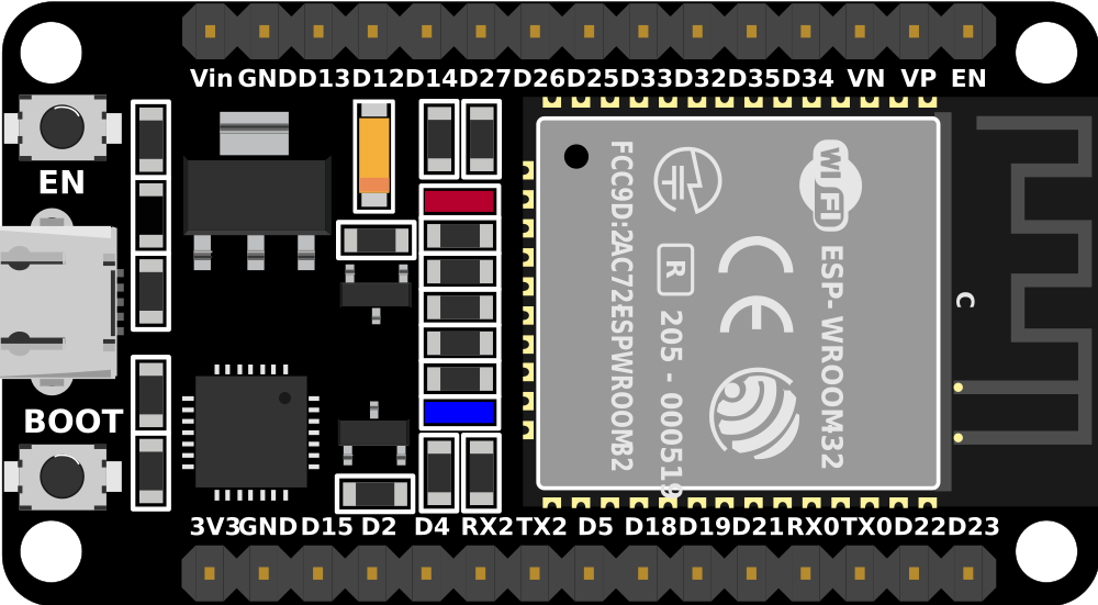
Pin Configuration and Descriptions

Pin Number Function Description
1-2 GND Ground
3 3V3 3.3V power supply
4 EN Reset pin, active low
5 VP GPIO36, ADC1_CH0, Sensor VP
6 VN GPIO39, ADC1_CH3, Sensor VN
7 IO34 GPIO34, ADC1_CH6, input only
8 IO35 GPIO35, ADC1_CH7, input only
9 IO32 GPIO32, ADC1_CH4, XTAL_32K
10 IO33 GPIO33, ADC1_CH5, XTAL_32K
11 IO25 GPIO25, ADC2_CH8, DAC_1
12 IO26 GPIO26, ADC2_CH9, DAC_2
13 IO27 GPIO27, ADC2_CH7
14 IO14 GPIO14, ADC2_CH6, Touch sensor
15 IO12 GPIO12, ADC2_CH5, Touch sensor, Bootstrapping
16 GND Ground
17 IO13 GPIO13, ADC2_CH4, Touch sensor
18 IO9 GPIO9, SD2
19 IO10 GPIO10, SD3
20 IO11 GPIO11, SD_CMD
21 IO6 GPIO6, SD_CLK
22 IO7 GPIO7, SD_DATA0
23 IO8 GPIO8, SD_DATA1
24 IO15 GPIO15, ADC2_CH3, Touch sensor, MTDO
25 IO2 GPIO2, ADC2_CH2, Touch sensor, TXD1
26 IO0 GPIO0, ADC2_CH1, Touch sensor, Boot
27 IO4 GPIO4, ADC2_CH0, Touch sensor, LED_BUILTIN
28 IO16 GPIO16, U2_RXD, HS1_DATA4
29 IO17 GPIO17, U2_TXD, HS1_DATA3
30 IO5 GPIO5, VSPICS0, HS1_DATA6

Usage Instructions

Integrating ESP32 into a Circuit

  1. Power Supply: Connect a 5V power supply to the VIN pin and GND to one of the ground pins. Alternatively, power the board via the micro-USB port.
  2. Reset: Pull the EN pin low to reset the board.
  3. GPIO Pins: Use the digital and analog pins to interface with sensors, actuators, and other components. Note that some pins have specific functions and may not be available for general use.
  4. Programming: Use the micro-USB port to connect the ESP32 to a computer for programming. The board is compatible with the Arduino IDE and other development environments.

Best Practices

  • Always ensure that the power supply is within the recommended voltage range to prevent damage.
  • When using Wi-Fi or Bluetooth, consider the antenna placement for optimal signal strength.
  • Avoid using GPIOs 6 to 11 as they are connected to the integrated SPI flash.
  • Use external pull-up or pull-down resistors with GPIOs if required by your circuit design.
  • Be cautious with GPIOs 34-39 as they are input-only and do not have software pull-up or pull-down circuitry.

Troubleshooting and FAQs

Common Issues

  • Board not powering up: Check the power supply and connections. Ensure the EN pin is not held low.
  • Cannot upload code: Verify the correct board and port are selected in the development environment. Ensure drivers are installed.
  • Wi-Fi/Bluetooth not functioning: Check antenna connections and ensure no metal objects are obstructing the signal.

Solutions and Tips

  • If the ESP32 is not recognized by the computer, try pressing the BOOT button when initiating the upload.
  • For analog readings, if you experience noise, ensure that the power supply is stable and use capacitors for decoupling if necessary.
  • If you encounter unexpected behavior, a full erase of the flash memory and reprogramming may resolve the issue.

Example Code for Arduino UNO

// Basic ESP32 Wi-Fi connection example
#include <WiFi.h>

const char* ssid = "yourSSID"; // Replace with your Wi-Fi SSID
const char* password = "yourPASSWORD"; // Replace with your Wi-Fi password

void setup() {
  Serial.begin(115200);
  // Connect to Wi-Fi
  WiFi.begin(ssid, password);
  while (WiFi.status() != WL_CONNECTED) {
    delay(500);
    Serial.println("Connecting to WiFi...");
  }
  Serial.println("Connected to WiFi");
}

void loop() {
  // Put your main code here, to run repeatedly:
}

Note: The ESP32 is not manufactured by Arduino, but it can be programmed using the Arduino IDE with the appropriate board package installed. The manufacturer part ID "proteus 8 demonstrat" does not correspond to the ESP32 and seems to be a misunderstanding. Proteus is a software suite for electronic design automation, and "Proteus 8 Demonstration" is likely a reference to a demo version of this software.