How to Use Bipolar Stepper Motor (NEMA 17): Examples, Pinouts, and Specs
Introduction
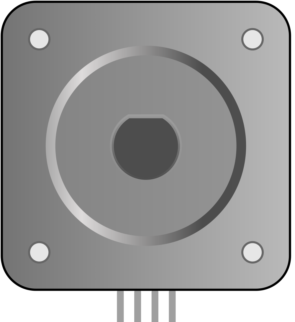
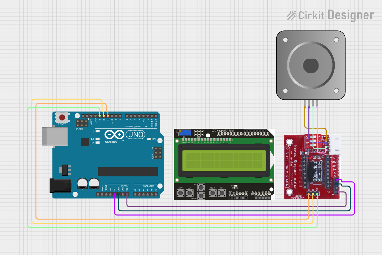
The Bipolar Stepper Motor (NEMA 17) is a type of stepper motor that uses two coils to generate magnetic fields, enabling precise control of rotation and position. The "NEMA 17" designation refers to the motor's faceplate dimensions, which measure 1.7 inches (43.2 mm) on each side. This motor is widely used in applications requiring accurate positioning, such as 3D printers, CNC machines, robotics, and automated systems. Its compact size, high torque, and reliability make it a popular choice for both hobbyists and professionals.
Explore Projects Built with Bipolar Stepper Motor (NEMA 17)
Explore Projects Built with Bipolar Stepper Motor (NEMA 17)
Technical Specifications
Below are the key technical details for a typical NEMA 17 bipolar stepper motor. Note that specific values may vary depending on the manufacturer and model.
General Specifications
- Step Angle: 1.8° (200 steps per revolution)
- Rated Voltage: 2.8V (varies by model)
- Rated Current: 1.2A per phase
- Holding Torque: 40 N·cm (varies by model)
- Number of Phases: 2
- Resistance per Phase: 2.4Ω
- Inductance per Phase: 3.2 mH
- Shaft Diameter: 5 mm
- Body Dimensions: 42.3 mm x 42.3 mm x 47 mm (excluding shaft)
- Weight: ~280 g
Pin Configuration and Descriptions
The NEMA 17 stepper motor typically has four wires, corresponding to the two coils (phases). The table below describes the pinout:
| Wire Color | Coil/Phase | Description |
|---|---|---|
| Red | A+ | Positive terminal of Coil A |
| Blue | A- | Negative terminal of Coil A |
| Green | B+ | Positive terminal of Coil B |
| Black | B- | Negative terminal of Coil B |
Note: Wire colors may vary depending on the manufacturer. Use a multimeter to verify coil pairs by checking continuity between wires.
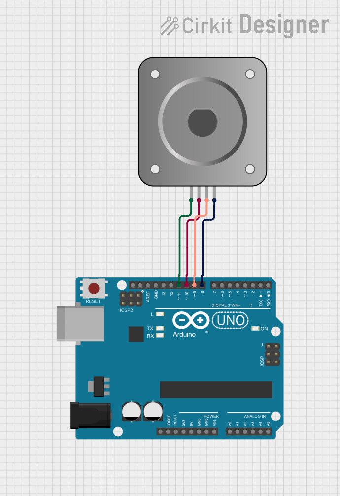
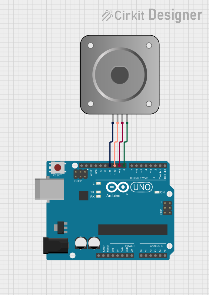
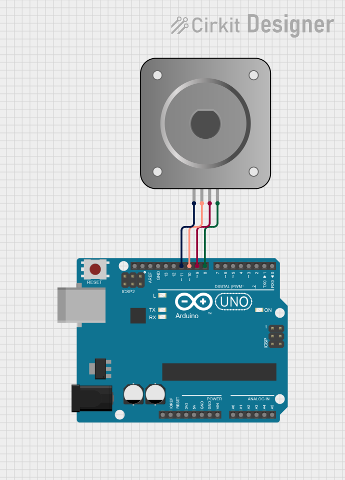
Usage Instructions
How to Use the Component in a Circuit
- Identify Coil Pairs: Use a multimeter to identify the two coil pairs. Check for continuity between wires to determine which wires belong to the same coil.
- Connect to a Driver: Use a stepper motor driver (e.g., A4988 or DRV8825) to control the motor. Connect the motor wires to the driver's output terminals (A+, A-, B+, B-).
- Power the Driver: Provide the appropriate voltage and current to the driver as specified in its datasheet. Ensure the power supply matches the motor's requirements.
- Control Signals: Use a microcontroller (e.g., Arduino UNO) to send step and direction signals to the driver. These signals control the motor's rotation and speed.
Important Considerations and Best Practices
- Current Limiting: Set the current limit on the driver to match the motor's rated current. This prevents overheating and damage to the motor.
- Power Supply: Use a power supply with sufficient voltage and current capacity. A higher voltage (within the driver's limits) can improve performance.
- Cooling: If the motor or driver becomes excessively hot, consider adding a heatsink or fan for cooling.
- Microstepping: Enable microstepping on the driver for smoother motion and higher resolution.
- Avoid Stalling: Do not exceed the motor's torque limits to prevent stalling or loss of steps.
Example Code for Arduino UNO
Below is an example of how to control a NEMA 17 stepper motor using an Arduino UNO and an A4988 driver:
// Include the Arduino Stepper library
#include <Stepper.h>

// Define the number of steps per revolution for the motor
#define STEPS_PER_REV 200

// Initialize the Stepper library with steps per revolution and pin connections
// Connect the A4988 driver's STEP and DIR pins to Arduino pins 3 and 4
Stepper stepper(STEPS_PER_REV, 3, 4);

void setup() {
  // Set the motor speed (in RPM)
  stepper.setSpeed(60); // 60 RPM

  // Print a message to the Serial Monitor
  Serial.begin(9600);
  Serial.println("Stepper motor control initialized.");
}

void loop() {
  // Rotate the motor 1 revolution clockwise
  Serial.println("Rotating clockwise...");
  stepper.step(STEPS_PER_REV);
  delay(1000); // Wait for 1 second

  // Rotate the motor 1 revolution counterclockwise
  Serial.println("Rotating counterclockwise...");
  stepper.step(-STEPS_PER_REV);
  delay(1000); // Wait for 1 second
}
Note: Ensure the A4988 driver's ENABLE pin is connected to GND to activate the motor.
Troubleshooting and FAQs
Common Issues and Solutions
Motor Not Moving:
- Verify the wiring between the motor, driver, and microcontroller.
- Check the power supply voltage and current.
- Ensure the driver is enabled (ENABLE pin connected to GND).
Motor Vibrates but Doesn't Rotate:
- Check the coil connections. Ensure each coil is connected to the correct driver terminals.
- Verify the step and direction signals from the microcontroller.
Overheating:
- Reduce the current limit on the driver.
- Add cooling (e.g., heatsink or fan) to the motor and driver.
Skipping Steps or Stalling:
- Increase the current limit (within the motor's rated current).
- Reduce the load on the motor or use a motor with higher torque.
FAQs
Can I run the NEMA 17 without a driver? No, a stepper motor driver is required to control the motor's step and direction signals.
What is microstepping, and why is it useful? Microstepping divides each full step into smaller steps, providing smoother motion and higher resolution.
Can I use a higher voltage power supply? Yes, as long as it is within the driver's voltage limits. Higher voltage improves performance but requires proper current limiting.
How do I determine the coil pairs if the wire colors are different? Use a multimeter to check continuity. Wires with continuity belong to the same coil.
By following this documentation, you can effectively use the NEMA 17 bipolar stepper motor in your projects!