How to Use Fan DC 12V: Examples, Pinouts, and Specs
Introduction
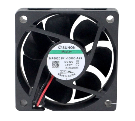
The Fan DC 12V is a direct current cooling fan designed to operate at a nominal voltage of 12 volts. It is widely used in electronic devices and enclosures to provide efficient airflow for heat dissipation. This component is essential for maintaining optimal operating temperatures in systems such as computers, power supplies, 3D printers, and other electronic equipment.
Explore Projects Built with Fan DC 12V

Explore Projects Built with Fan DC 12V
Common Applications and Use Cases
- Cooling computer processors, graphics cards, and power supplies
- Ventilation in enclosures for electronic circuits
- Heat dissipation in 3D printers and other industrial equipment
- General-purpose cooling in DIY electronics projects
Technical Specifications
The following table outlines the key technical specifications of the Fan DC 12V:
| Parameter | Value |
|---|---|
| Operating Voltage | 12V DC |
| Operating Current | 0.1A to 0.5A (varies by model) |
| Power Consumption | 1.2W to 6W |
| Airflow | 20 to 80 CFM (Cubic Feet/Minute) |
| Speed | 2000 to 5000 RPM |
| Noise Level | 20 to 40 dBA |
| Bearing Type | Sleeve or Ball Bearing |
| Dimensions | Common sizes: 40x40mm, 80x80mm, 120x120mm |
| Connector Type | 2-pin or 3-pin |
| Lifespan | 30,000 to 50,000 hours |
Pin Configuration and Descriptions
The Fan DC 12V typically comes with either a 2-pin or 3-pin connector. The pin configuration is as follows:
2-Pin Connector
| Pin Number | Wire Color | Description |
|---|---|---|
| 1 | Red | Positive (+12V) |
| 2 | Black | Ground (GND) |
3-Pin Connector
| Pin Number | Wire Color | Description |
|---|---|---|
| 1 | Red | Positive (+12V) |
| 2 | Black | Ground (GND) |
| 3 | Yellow | Tachometer (Speed Signal) |
Usage Instructions
How to Use the Fan DC 12V in a Circuit
- Power Supply: Connect the red wire to a 12V DC power source and the black wire to ground. Ensure the power supply can provide sufficient current for the fan's operation.
- Mounting: Secure the fan to the desired location using screws or adhesive mounts. Ensure the airflow direction aligns with the cooling requirements.
- Optional Speed Monitoring: If using a 3-pin fan, connect the yellow wire to a microcontroller or monitoring circuit to read the fan's speed (RPM).
Important Considerations and Best Practices
- Voltage Tolerance: Do not exceed the rated 12V DC input to avoid damaging the fan.
- Current Rating: Ensure the power supply can handle the fan's current draw, especially for high-speed models.
- Airflow Direction: Check the fan's label or markings to determine the airflow direction (usually indicated by arrows).
- Noise Reduction: Use rubber mounts or grommets to minimize vibration and noise.
- Dust and Maintenance: Periodically clean the fan blades to prevent dust buildup, which can reduce efficiency and increase noise.
Example: Connecting to an Arduino UNO
The Fan DC 12V can be controlled using an Arduino UNO and a transistor for switching. Below is an example circuit and code to control the fan's speed using PWM (Pulse Width Modulation):
Circuit Diagram
- Connect the fan's red wire to the collector of an NPN transistor (e.g., 2N2222).
- Connect the fan's black wire to ground.
- Connect the emitter of the transistor to ground.
- Connect a 1kΩ resistor between the Arduino's PWM pin (e.g., pin 9) and the transistor's base.
- Connect the Arduino's ground to the power supply ground.
Arduino Code
// Fan DC 12V Speed Control using PWM
// Connect the fan to a transistor circuit as described above.
// Ensure the fan's power supply matches its voltage and current requirements.

const int fanPin = 9; // PWM pin connected to the transistor's base

void setup() {
  pinMode(fanPin, OUTPUT); // Set the fan pin as an output
}

void loop() {
  // Gradually increase fan speed
  for (int speed = 0; speed <= 255; speed += 5) {
    analogWrite(fanPin, speed); // Set PWM duty cycle
    delay(50); // Wait 50ms before increasing speed
  }

  // Gradually decrease fan speed
  for (int speed = 255; speed >= 0; speed -= 5) {
    analogWrite(fanPin, speed); // Set PWM duty cycle
    delay(50); // Wait 50ms before decreasing speed
  }
}
Troubleshooting and FAQs
Common Issues and Solutions
Fan Does Not Spin
- Cause: Insufficient power supply or incorrect wiring.
- Solution: Verify the power supply voltage and current. Check the wiring connections.
Fan Spins Slowly
- Cause: Low input voltage or excessive dust buildup.
- Solution: Ensure the input voltage is 12V. Clean the fan blades and vents.
Excessive Noise
- Cause: Vibration or worn-out bearings.
- Solution: Use rubber mounts to reduce vibration. Replace the fan if bearings are damaged.
Fan Speed Not Detected (3-Pin Fan)
- Cause: Tachometer wire not connected or incompatible monitoring circuit.
- Solution: Verify the yellow wire connection. Ensure the monitoring circuit supports tachometer signals.
FAQs
Q: Can I use a 12V fan with a 5V power supply?
A: No, a 5V power supply will not provide sufficient voltage for the fan to operate correctly. Use a 12V power source.
Q: How do I reverse the airflow direction?
A: To reverse airflow, physically flip the fan. Do not reverse the polarity of the power connections, as this may damage the fan.
Q: Can I control the fan speed without a microcontroller?
A: Yes, you can use a variable resistor (potentiometer) or a dedicated fan speed controller circuit to adjust the voltage supplied to the fan.