Cirkit Designer Logo
Cirkit Designer
Your all-in-one circuit design IDE
Home / 
Component Documentation

How to Use Color Sensing Detection Sensor: Examples, Pinouts, and Specs

Image of Color Sensing Detection Sensor
Cirkit Designer LogoDesign with Color Sensing Detection Sensor in Cirkit Designer

Introduction

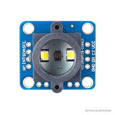
The GY-33 Color Sensing Detection Sensor, manufactured by Gui Yi, is a versatile and reliable sensor designed to detect and identify colors in its environment. This sensor is widely used in various applications, including robotics, automation, and quality control. Its ability to accurately sense colors makes it an essential component in projects that require color differentiation and recognition.

Explore Projects Built with Color Sensing Detection Sensor

Use Cirkit Designer to design, explore, and prototype these projects online. Some projects support real-time simulation. Click "Open Project" to start designing instantly!
Arduino UNO and AS7262 Color Change Detection System with Bluetooth and OLED Display
Image of CAR project: A project utilizing Color Sensing Detection Sensor in a practical application
This circuit is designed to detect color changes in a solution using a spectral sensor, time the change, provide a sound cue via a piezo buzzer, and send the timing data to a computer via a Bluetooth module. The Arduino UNO microcontroller coordinates the sensor readings, timing, and communication, while an OLED display and NeoPixel ring provide visual feedback.
Cirkit Designer LogoOpen Project in Cirkit Designer
Arduino UNO with TCS34725 Color Sensor and LDR Light Detection
Image of SSC: A project utilizing Color Sensing Detection Sensor in a practical application
This circuit features an Arduino UNO microcontroller connected to an Adafruit TCS34725 RGB Color Sensor and a photocell (LDR) with a 10k Ohm resistor forming a voltage divider connected to the Arduino's analog input A0. The RGB sensor is interfaced with the Arduino via I2C communication, using SDA and SCL lines. The purpose of this circuit is likely to measure ambient light intensity with the photocell and detect colors with the RGB sensor, both interfaced with the Arduino for processing and potential output of the sensor data.
Cirkit Designer LogoOpen Project in Cirkit Designer
Arduino Nano-Controlled Lighting System with Gesture and Sound Interaction
Image of 4 load controll using hand gesture and sound controll: A project utilizing Color Sensing Detection Sensor in a practical application
This circuit features an Arduino Nano microcontroller interfaced with an APDS-9960 RGB and Gesture Sensor for color and gesture detection, and a KY-038 microphone module for sound detection. The Arduino controls a 4-channel relay module, which in turn switches four AC bulbs on and off. The 12V power supply is used to power the relay module, and the bulbs are connected to the normally open (N.O.) contacts of the relays, allowing the Arduino to control the lighting based on sensor inputs.
Cirkit Designer LogoOpen Project in Cirkit Designer
Arduino UNO-Based Color Sensor and Proximity Detection System with TCS3200 and Inductive Sensor
Image of 404 Wiring Schematic: A project utilizing Color Sensing Detection Sensor in a practical application
This circuit integrates an Arduino UNO with a TCS3200 color sensor and an LJ18A3-H-ZBX inductive proximity sensor to detect colors and proximity. The Arduino processes the sensor data and controls an LED indicator, with resistors used for current limiting.
Cirkit Designer LogoOpen Project in Cirkit Designer

Explore Projects Built with Color Sensing Detection Sensor

Use Cirkit Designer to design, explore, and prototype these projects online. Some projects support real-time simulation. Click "Open Project" to start designing instantly!
Image of CAR project: A project utilizing Color Sensing Detection Sensor in a practical application
Arduino UNO and AS7262 Color Change Detection System with Bluetooth and OLED Display
This circuit is designed to detect color changes in a solution using a spectral sensor, time the change, provide a sound cue via a piezo buzzer, and send the timing data to a computer via a Bluetooth module. The Arduino UNO microcontroller coordinates the sensor readings, timing, and communication, while an OLED display and NeoPixel ring provide visual feedback.
Cirkit Designer LogoOpen Project in Cirkit Designer
Image of SSC: A project utilizing Color Sensing Detection Sensor in a practical application
Arduino UNO with TCS34725 Color Sensor and LDR Light Detection
This circuit features an Arduino UNO microcontroller connected to an Adafruit TCS34725 RGB Color Sensor and a photocell (LDR) with a 10k Ohm resistor forming a voltage divider connected to the Arduino's analog input A0. The RGB sensor is interfaced with the Arduino via I2C communication, using SDA and SCL lines. The purpose of this circuit is likely to measure ambient light intensity with the photocell and detect colors with the RGB sensor, both interfaced with the Arduino for processing and potential output of the sensor data.
Cirkit Designer LogoOpen Project in Cirkit Designer
Image of 4 load controll using hand gesture and sound controll: A project utilizing Color Sensing Detection Sensor in a practical application
Arduino Nano-Controlled Lighting System with Gesture and Sound Interaction
This circuit features an Arduino Nano microcontroller interfaced with an APDS-9960 RGB and Gesture Sensor for color and gesture detection, and a KY-038 microphone module for sound detection. The Arduino controls a 4-channel relay module, which in turn switches four AC bulbs on and off. The 12V power supply is used to power the relay module, and the bulbs are connected to the normally open (N.O.) contacts of the relays, allowing the Arduino to control the lighting based on sensor inputs.
Cirkit Designer LogoOpen Project in Cirkit Designer
Image of 404 Wiring Schematic: A project utilizing Color Sensing Detection Sensor in a practical application
Arduino UNO-Based Color Sensor and Proximity Detection System with TCS3200 and Inductive Sensor
This circuit integrates an Arduino UNO with a TCS3200 color sensor and an LJ18A3-H-ZBX inductive proximity sensor to detect colors and proximity. The Arduino processes the sensor data and controls an LED indicator, with resistors used for current limiting.
Cirkit Designer LogoOpen Project in Cirkit Designer

Technical Specifications

Key Technical Details

Parameter Value
Operating Voltage 3.3V - 5V
Operating Current 10mA
Communication I2C
Color Sensing Range 380nm to 780nm (visible light)
Dimensions 20mm x 20mm x 3.2mm
Manufacturer Gui Yi
Part ID GY-33

Pin Configuration and Descriptions

Pin Number Pin Name Description
1 VCC Power supply (3.3V - 5V)
2 GND Ground
3 SDA I2C data line
4 SCL I2C clock line
5 INT Interrupt output (optional, for advanced usage)

Usage Instructions

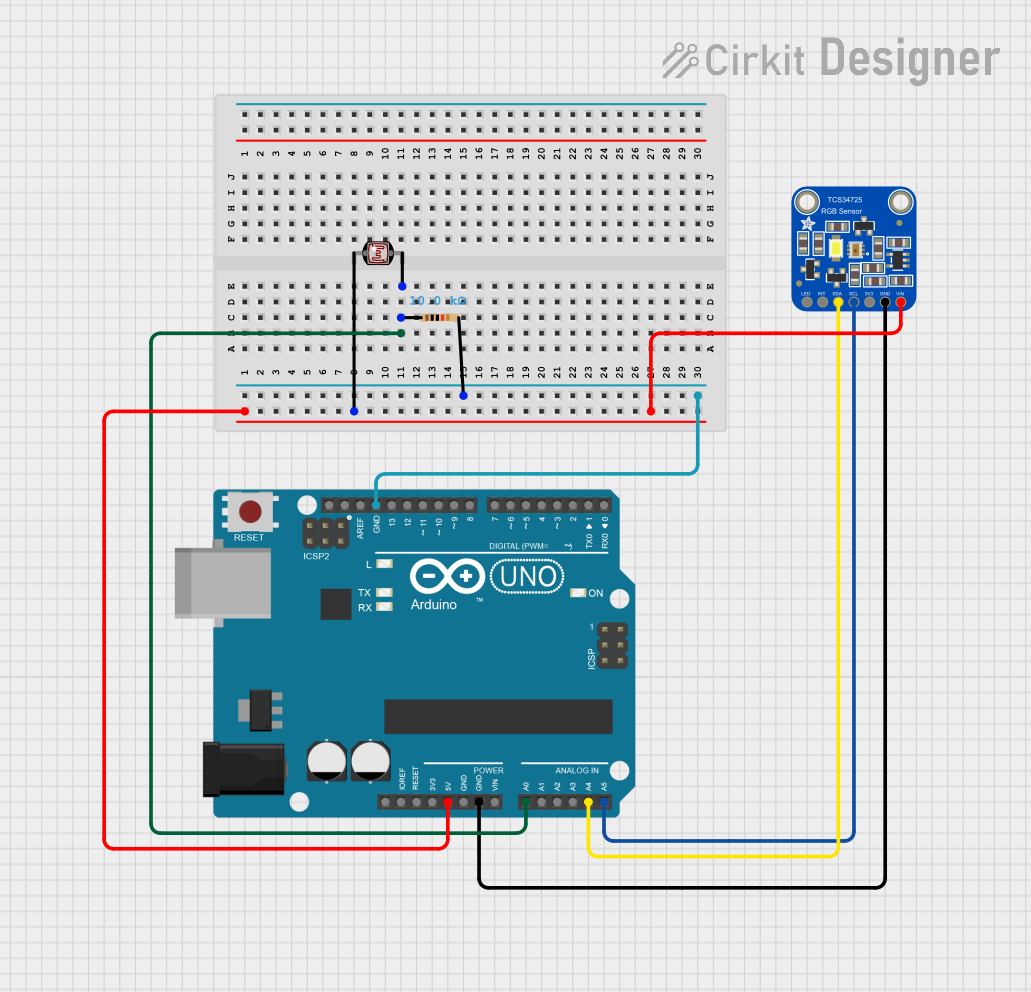
How to Use the GY-33 in a Circuit

  1. Power Supply: Connect the VCC pin to a 3.3V or 5V power supply and the GND pin to the ground of your circuit.
  2. I2C Communication: Connect the SDA pin to the SDA pin on your microcontroller (e.g., Arduino UNO) and the SCL pin to the SCL pin on your microcontroller.
  3. Optional Interrupt: If you wish to use the interrupt feature, connect the INT pin to a digital input pin on your microcontroller.

Important Considerations and Best Practices

  • Power Supply: Ensure that the power supply voltage is within the specified range (3.3V - 5V) to avoid damaging the sensor.
  • I2C Pull-up Resistors: If your microcontroller does not have internal pull-up resistors on the I2C lines, you may need to add external pull-up resistors (typically 4.7kΩ) between the SDA/SCL lines and the VCC.
  • Ambient Light: The sensor's accuracy can be affected by ambient light conditions. For best results, use the sensor in a controlled lighting environment or calibrate it according to the ambient light.

Sample Arduino Code

Below is a sample Arduino code to interface the GY-33 Color Sensing Detection Sensor with an Arduino UNO:

#include <Wire.h>

// GY-33 I2C address
#define GY33_ADDRESS 0x39

void setup() {
  Serial.begin(9600); // Initialize serial communication
  Wire.begin();       // Initialize I2C communication

  // Initialize the GY-33 sensor
  Wire.beginTransmission(GY33_ADDRESS);
  Wire.write(0x00); // Write to the control register
  Wire.write(0x01); // Power on the sensor
  Wire.endTransmission();
}

void loop() {
  uint16_t red, green, blue, clear;

  // Request color data from the sensor
  Wire.beginTransmission(GY33_ADDRESS);
  Wire.write(0x0C); // Command to read color data
  Wire.endTransmission();
  Wire.requestFrom(GY33_ADDRESS, 8);

  // Read the color data
  clear = Wire.read() | (Wire.read() << 8);
  red = Wire.read() | (Wire.read() << 8);
  green = Wire.read() | (Wire.read() << 8);
  blue = Wire.read() | (Wire.read() << 8);

  // Print the color data to the serial monitor
  Serial.print("Red: ");
  Serial.print(red);
  Serial.print(" Green: ");
  Serial.print(green);
  Serial.print(" Blue: ");
  Serial.print(blue);
  Serial.print(" Clear: ");
  Serial.println(clear);

  delay(1000); // Wait for 1 second before the next reading
}

Troubleshooting and FAQs

Common Issues and Solutions

  1. No Data Output:

    • Solution: Ensure that the sensor is properly connected to the power supply and the I2C lines. Check for loose connections and verify that the correct I2C address is used in the code.
  2. Inaccurate Color Readings:

    • Solution: Calibrate the sensor according to the ambient light conditions. Ensure that there are no strong light sources directly affecting the sensor.
  3. I2C Communication Errors:

    • Solution: Check the pull-up resistors on the SDA and SCL lines. Ensure that the I2C lines are not too long and are properly shielded from electrical noise.

FAQs

Q1: Can the GY-33 sensor detect colors in low light conditions?

  • A1: The GY-33 sensor can detect colors in low light conditions, but its accuracy may be affected. It is recommended to use the sensor in a controlled lighting environment for best results.

Q2: What is the maximum distance at which the GY-33 sensor can detect colors?

  • A2: The GY-33 sensor is designed to detect colors at a close range, typically within a few centimeters. The exact distance may vary depending on the color and lighting conditions.

Q3: Can I use multiple GY-33 sensors on the same I2C bus?

  • A3: Yes, you can use multiple GY-33 sensors on the same I2C bus, but each sensor must have a unique I2C address. You may need to modify the sensor's address if they are the same by default.

This documentation provides a comprehensive guide to using the GY-33 Color Sensing Detection Sensor. By following the instructions and best practices outlined here, you can effectively integrate this sensor into your projects and achieve accurate color detection and identification.