
How to Use SparkFun OBD-II UART: Examples, Pinouts, and Specs
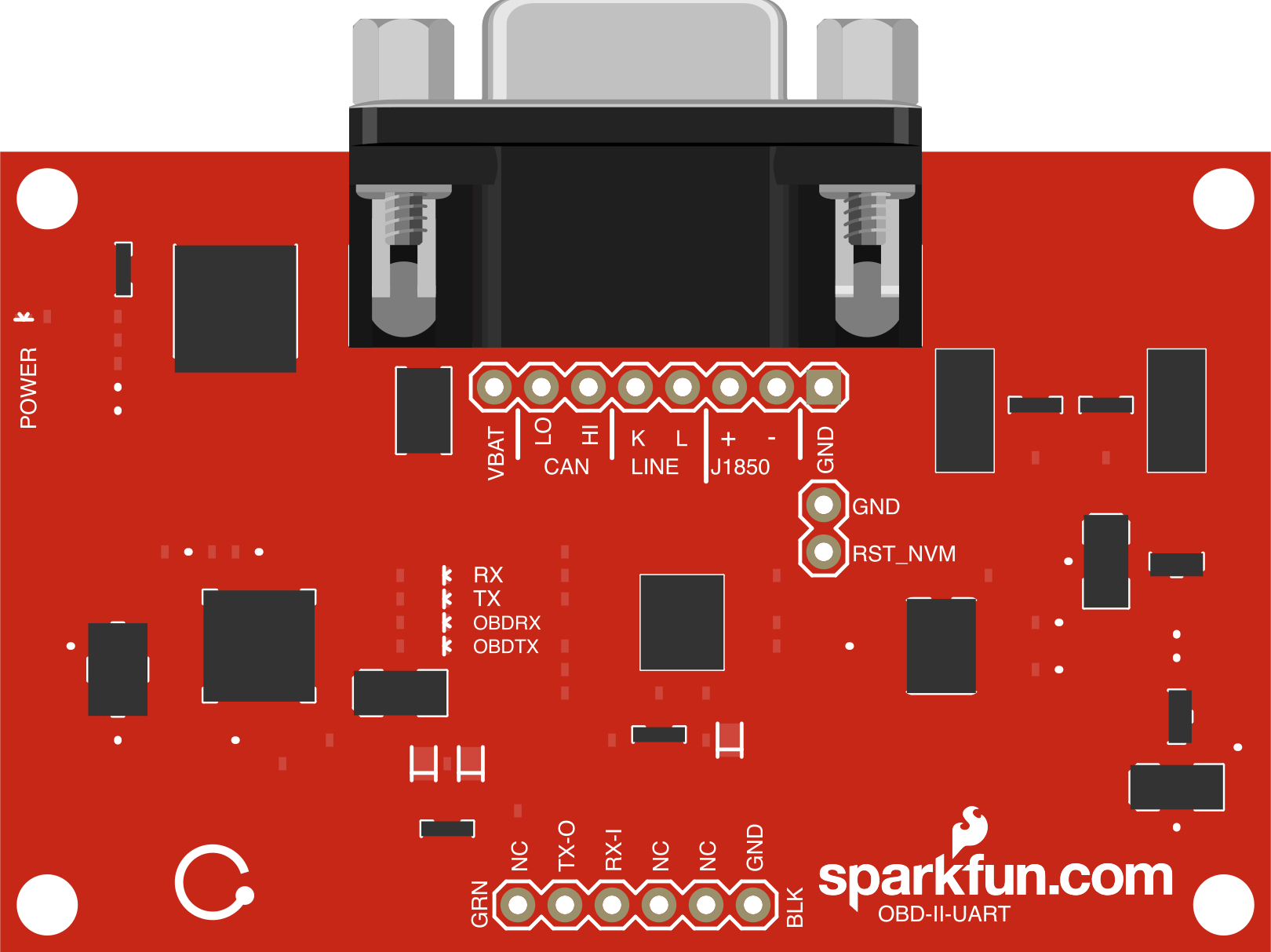
 Design with SparkFun OBD-II UART in Cirkit Designer
Introduction
The SparkFun OBD-II UART (Manufacturer Part ID: WIG-09555) is a compact interface module designed to facilitate communication with OBD-II compliant vehicles. It provides a UART interface, enabling users to access vehicle diagnostics, sensor data, and other critical information from the vehicle's onboard computer. This module is ideal for automotive diagnostics, data logging, and vehicle performance monitoring.
Explore Projects Built with SparkFun OBD-II UART
 Open Project in Cirkit Designer
 Open Project in Cirkit Designer
 Open Project in Cirkit Designer
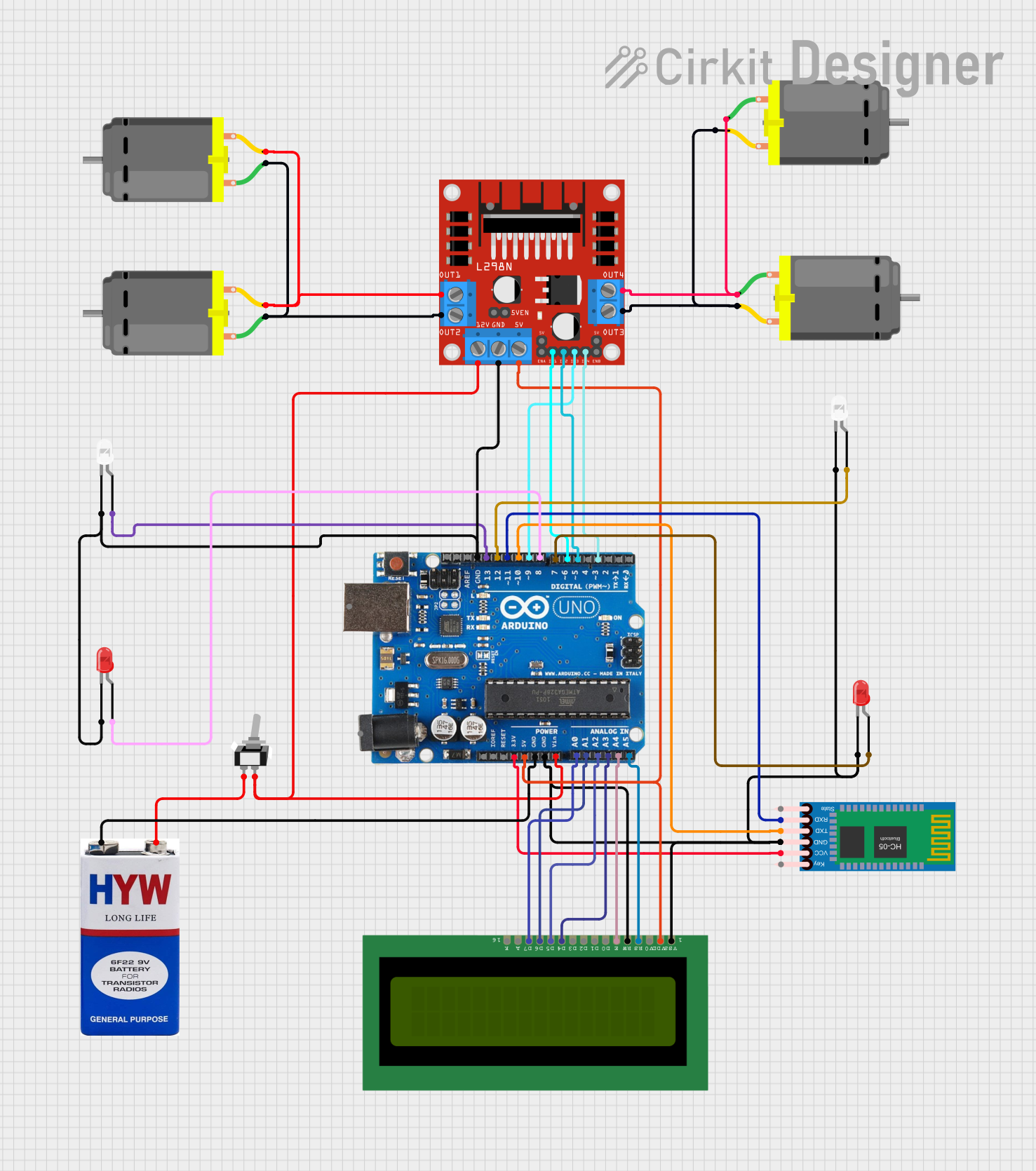 Open Project in Cirkit Designer
Explore Projects Built with SparkFun OBD-II UART
Open Project in Cirkit DesignerOpen Project in Cirkit DesignerOpen Project in Cirkit DesignerOpen Project in Cirkit DesignerCommon Applications
- Reading and clearing diagnostic trouble codes (DTCs)
- Monitoring real-time vehicle sensor data (e.g., speed, RPM, temperature)
- Developing custom automotive applications
- Vehicle performance analysis and tuning
- Educational projects related to automotive systems
Technical Specifications
The following table outlines the key technical details of the SparkFun OBD-II UART module:
| Parameter | Specification |
|---|---|
| Supply Voltage | 5V (via UART interface or external power source) |
| Communication Protocol | UART (9600 bps default, configurable) |
| OBD-II Protocol Support | ISO15765-4 (CAN), ISO9141-2, ISO14230-4 (KWP2000), SAE J1850 VPW, SAE J1850 PWM |
| Operating Temperature | -40°C to +85°C |
| Dimensions | 1.8" x 1.2" (45.7mm x 30.5mm) |
| Connector Type | DB9 (OBD-II) and 6-pin UART header |
Pin Configuration
The module features a 6-pin UART header for interfacing with microcontrollers or other devices. The pin configuration is as follows:
| Pin | Name | Description |
|---|---|---|
| 1 | GND | Ground |
| 2 | VCC | Power supply input (5V) |
| 3 | TX | UART Transmit (data from module to host) |
| 4 | RX | UART Receive (data from host to module) |
| 5 | RTS | Request to Send (optional, for flow control) |
| 6 | CTS | Clear to Send (optional, for flow control) |
Usage Instructions
Connecting the Module
- Power Supply: Connect the
VCCpin to a 5V power source and theGNDpin to ground. - UART Interface: Connect the
TXpin of the module to theRXpin of your microcontroller, and theRXpin of the module to theTXpin of your microcontroller. - OBD-II Connector: Plug the DB9 connector into the OBD-II port of your vehicle.
- Optional Flow Control: If required, connect the
RTSandCTSpins for hardware flow control.
Using with Arduino UNO
The SparkFun OBD-II UART module can be easily interfaced with an Arduino UNO. Below is an example code snippet to read data from the module:
#include <SoftwareSerial.h>

// Define RX and TX pins for SoftwareSerial
SoftwareSerial obdSerial(10, 11); // RX = pin 10, TX = pin 11

void setup() {
  Serial.begin(9600); // Initialize hardware serial for debugging
  obdSerial.begin(9600); // Initialize OBD-II UART communication

  Serial.println("Initializing OBD-II UART...");
  delay(1000); // Allow time for initialization
}

void loop() {
  // Check if data is available from the OBD-II module
  if (obdSerial.available()) {
    String obdData = ""; // Variable to store incoming data

    // Read all available data from the module
    while (obdSerial.available()) {
      char c = obdSerial.read();
      obdData += c;
    }

    // Print the received data to the Serial Monitor
    Serial.println("OBD-II Data: " + obdData);
  }

  delay(500); // Delay to avoid flooding the Serial Monitor
}
Important Considerations
- Ensure the vehicle is OBD-II compliant before connecting the module.
- Use a stable 5V power source to avoid damaging the module.
- Configure the UART baud rate if the default (9600 bps) does not match your application.
- Avoid connecting or disconnecting the module while the vehicle is powered on.
Troubleshooting and FAQs
Common Issues
No Data Received from the Module
- Ensure the
TXandRXpins are correctly connected. - Verify that the vehicle is OBD-II compliant.
- Check the baud rate settings of your microcontroller and the module.
- Ensure the
Module Not Powering On
- Confirm that the
VCCpin is receiving a stable 5V supply. - Check the ground connection.
- Confirm that the
Unrecognized OBD-II Protocol
- Ensure the vehicle supports one of the protocols listed in the specifications.
- Try resetting the module and reconnecting.
Data Corruption or Incomplete Data
- Use shorter UART cables to reduce noise.
- Enable hardware flow control by connecting the
RTSandCTSpins.
FAQs
Q: Can this module be used with a Raspberry Pi?
A: Yes, the module can be connected to a Raspberry Pi via its UART pins. Ensure proper voltage level shifting if required.
Q: How do I change the UART baud rate?
A: The baud rate can be configured by sending specific AT commands to the module. Refer to the manufacturer's datasheet for details.
Q: Is the module compatible with electric vehicles (EVs)?
A: The module can access OBD-II data from EVs if they support standard OBD-II protocols. However, some EVs may use proprietary protocols.
Q: Can I use this module for real-time data logging?
A: Yes, the module is suitable for real-time data logging when paired with a microcontroller or computer.
By following this documentation, users can effectively integrate the SparkFun OBD-II UART module into their projects and access valuable vehicle data.