How to Use ESP32: Examples, Pinouts, and Specs
Introduction
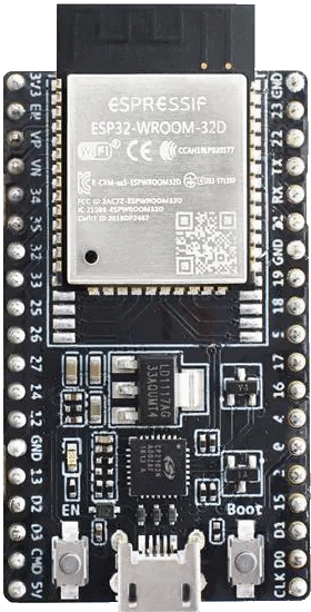
The ESP32, manufactured by Espressif Systems, is a powerful and versatile microcontroller that integrates Wi-Fi and Bluetooth capabilities. Designed for IoT (Internet of Things) applications and embedded systems, the ESP32 offers high performance, low power consumption, and a wide range of features. It is widely used in smart home devices, wearables, industrial automation, and other connected applications.
Explore Projects Built with ESP32


Explore Projects Built with ESP32
Common Applications and Use Cases
- IoT devices and smart home automation
- Wireless sensor networks
- Wearable electronics
- Industrial control systems
- Robotics and drones
- Audio streaming and voice recognition systems
Technical Specifications
The ESP32 is a highly integrated microcontroller with the following key technical specifications:
| Parameter | Specification |
|---|---|
| Manufacturer | Espressif Systems |
| Part ID | ESP32 |
| Processor | Dual-core Xtensa® 32-bit LX6 microprocessor |
| Clock Speed | Up to 240 MHz |
| Flash Memory | 4 MB (varies by module) |
| SRAM | 520 KB |
| Wireless Connectivity | Wi-Fi 802.11 b/g/n, Bluetooth v4.2 + BLE |
| Operating Voltage | 3.0V to 3.6V |
| GPIO Pins | Up to 34 GPIO pins |
| ADC Channels | 18 (12-bit resolution) |
| DAC Channels | 2 (8-bit resolution) |
| Communication Interfaces | UART, SPI, I2C, I2S, CAN, PWM |
| Power Consumption | Ultra-low power consumption in deep sleep mode (as low as 10 µA) |
| Operating Temperature Range | -40°C to +85°C |
Pin Configuration and Descriptions
The ESP32 has a flexible pinout, with multiple pins supporting various functions. Below is a general description of the pin configuration:
| Pin Name | Function | Description |
|---|---|---|
| GPIO0 | Input/Output, Boot Mode Selection | Used for boot mode selection during startup. |
| GPIO2 | Input/Output, ADC, PWM | General-purpose I/O, supports ADC and PWM. |
| GPIO12 | Input/Output, ADC, Touch Sensor | General-purpose I/O, supports ADC and capacitive touch sensing. |
| GPIO13 | Input/Output, ADC, Touch Sensor | General-purpose I/O, supports ADC and capacitive touch sensing. |
| GPIO15 | Input/Output, ADC, PWM | General-purpose I/O, supports ADC and PWM. |
| EN | Enable | Active-high enable pin for the ESP32. |
| 3V3 | Power | 3.3V power supply input. |
| GND | Ground | Ground connection. |
| TX0 | UART Transmit | UART0 transmit pin for serial communication. |
| RX0 | UART Receive | UART0 receive pin for serial communication. |
Note: The exact pinout may vary depending on the specific ESP32 module or development board being used.
Usage Instructions
How to Use the ESP32 in a Circuit
- Power Supply: Provide a stable 3.3V power supply to the ESP32. Avoid exceeding the maximum voltage of 3.6V to prevent damage.
- Boot Mode: Connect GPIO0 to GND during startup to enter bootloader mode for programming.
- GPIO Usage: Configure GPIO pins as input or output in your code. Be mindful of pins with special functions (e.g., ADC, PWM).
- Communication Interfaces: Use UART, SPI, or I2C for communication with other devices. Ensure proper pull-up resistors for I2C lines.
- Wi-Fi and Bluetooth: Use the built-in Wi-Fi and Bluetooth libraries to connect to networks or pair with other devices.
Important Considerations and Best Practices
- Voltage Levels: Ensure all connected peripherals operate at 3.3V logic levels. Use level shifters if interfacing with 5V devices.
- Deep Sleep Mode: Utilize the deep sleep mode to reduce power consumption in battery-powered applications.
- Antenna Placement: For optimal wireless performance, ensure the onboard antenna is not obstructed by metal or other conductive materials.
- Heat Management: The ESP32 may generate heat during operation. Ensure proper ventilation or heat dissipation in high-performance applications.
Example Code for Arduino UNO Integration
The ESP32 can be programmed using the Arduino IDE. Below is an example of how to connect the ESP32 to a Wi-Fi network:
#include <WiFi.h> // Include the Wi-Fi library for ESP32

const char* ssid = "Your_SSID";       // Replace with your Wi-Fi network name
const char* password = "Your_Password"; // Replace with your Wi-Fi password

void setup() {
  Serial.begin(115200); // Initialize serial communication at 115200 baud
  delay(1000);          // Wait for a moment before starting

  Serial.println("Connecting to Wi-Fi...");
  WiFi.begin(ssid, password); // Start connecting to the Wi-Fi network

  while (WiFi.status() != WL_CONNECTED) {
    delay(500); // Wait for the connection to establish
    Serial.print(".");
  }

  Serial.println("\nWi-Fi connected!");
  Serial.print("IP Address: ");
  Serial.println(WiFi.localIP()); // Print the assigned IP address
}

void loop() {
  // Add your main code here
}
Note: Replace
Your_SSIDandYour_Passwordwith your Wi-Fi credentials.
Troubleshooting and FAQs
Common Issues and Solutions
ESP32 Not Connecting to Wi-Fi
- Solution: Double-check the SSID and password. Ensure the Wi-Fi network is operational and within range.
- Tip: Use
WiFi.status()to debug connection issues.
GPIO Pins Not Responding
- Solution: Verify the pin configuration in your code. Ensure no conflicting functions are assigned to the same pin.
- Tip: Avoid using GPIO6-GPIO11 as they are reserved for flash memory.
ESP32 Overheating
- Solution: Reduce the clock speed or optimize your code to minimize processing load.
- Tip: Ensure proper ventilation and avoid placing the ESP32 in enclosed spaces.
Upload Fails in Arduino IDE
- Solution: Check the selected board and COM port in the Arduino IDE. Ensure the ESP32 is in bootloader mode (GPIO0 connected to GND).
- Tip: Install the latest ESP32 board package in the Arduino IDE.
FAQs
Q: Can the ESP32 operate on battery power?
- A: Yes, the ESP32 can operate on battery power. Use a 3.7V LiPo battery with a voltage regulator to provide a stable 3.3V supply.
Q: How do I reset the ESP32?
- A: Press the reset button on the development board or toggle the EN pin.
Q: Can I use the ESP32 with 5V peripherals?
- A: No, the ESP32 operates at 3.3V logic levels. Use level shifters to interface with 5V peripherals.
This documentation provides a comprehensive guide to understanding and using the ESP32 microcontroller effectively.