How to Use ACB: Examples, Pinouts, and Specs
Introduction
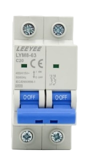
An Air Circuit Breaker (ACB) is a type of electrical device designed to protect electrical circuits from overloads and short circuits. It operates by automatically disconnecting the circuit when a fault is detected, ensuring the safety of electrical systems and preventing damage to connected equipment. ACBs are commonly used in industrial and commercial power distribution systems where high current ratings are required.
Explore Projects Built with ACB


Explore Projects Built with ACB
Common Applications and Use Cases
- Protection of industrial power distribution systems
- Circuit isolation in commercial buildings
- Backup protection for transformers, generators, and motors
- Overload and short-circuit protection in high-current systems
Technical Specifications
Key Technical Details
| Parameter | Value/Range |
|---|---|
| Rated Voltage | Up to 690V AC |
| Rated Current | 630A to 6300A |
| Breaking Capacity | 50kA to 100kA |
| Operating Mechanism | Manual or Motorized |
| Frequency | 50Hz or 60Hz |
| Insulation Medium | Air |
| Trip Unit Type | Electronic or Thermal-Magnetic |
| Operating Temperature | -5°C to +55°C |
| Mounting Type | Fixed or Withdrawable |
Pin Configuration and Descriptions
Air Circuit Breakers do not have traditional "pins" like smaller electronic components. Instead, they feature terminals for power connections and auxiliary contacts for control and monitoring. Below is a description of the key terminals and contacts:
| Terminal/Contact | Description |
|---|---|
| Line Terminals | Connect to the incoming power supply (L1, L2, L3 for three-phase systems). |
| Load Terminals | Connect to the outgoing load circuit. |
| Auxiliary Contacts | Provide status signals (e.g., ON/OFF, tripped) for remote monitoring. |
| Trip Coil Terminals | Used to connect the trip coil for remote tripping. |
| Control Terminals | Connect to control circuits for motorized operation or interlocking. |
Usage Instructions
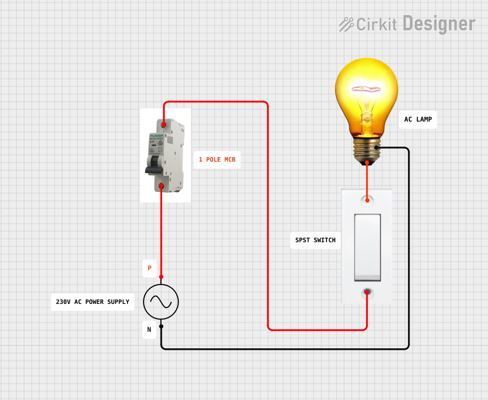
How to Use the Component in a Circuit
- Selection: Choose an ACB with appropriate voltage, current, and breaking capacity ratings for your application.
- Installation:
- Mount the ACB securely in the designated panel or enclosure.
- Connect the line terminals to the incoming power supply and the load terminals to the outgoing circuit.
- Ensure all connections are tight and secure to prevent overheating.
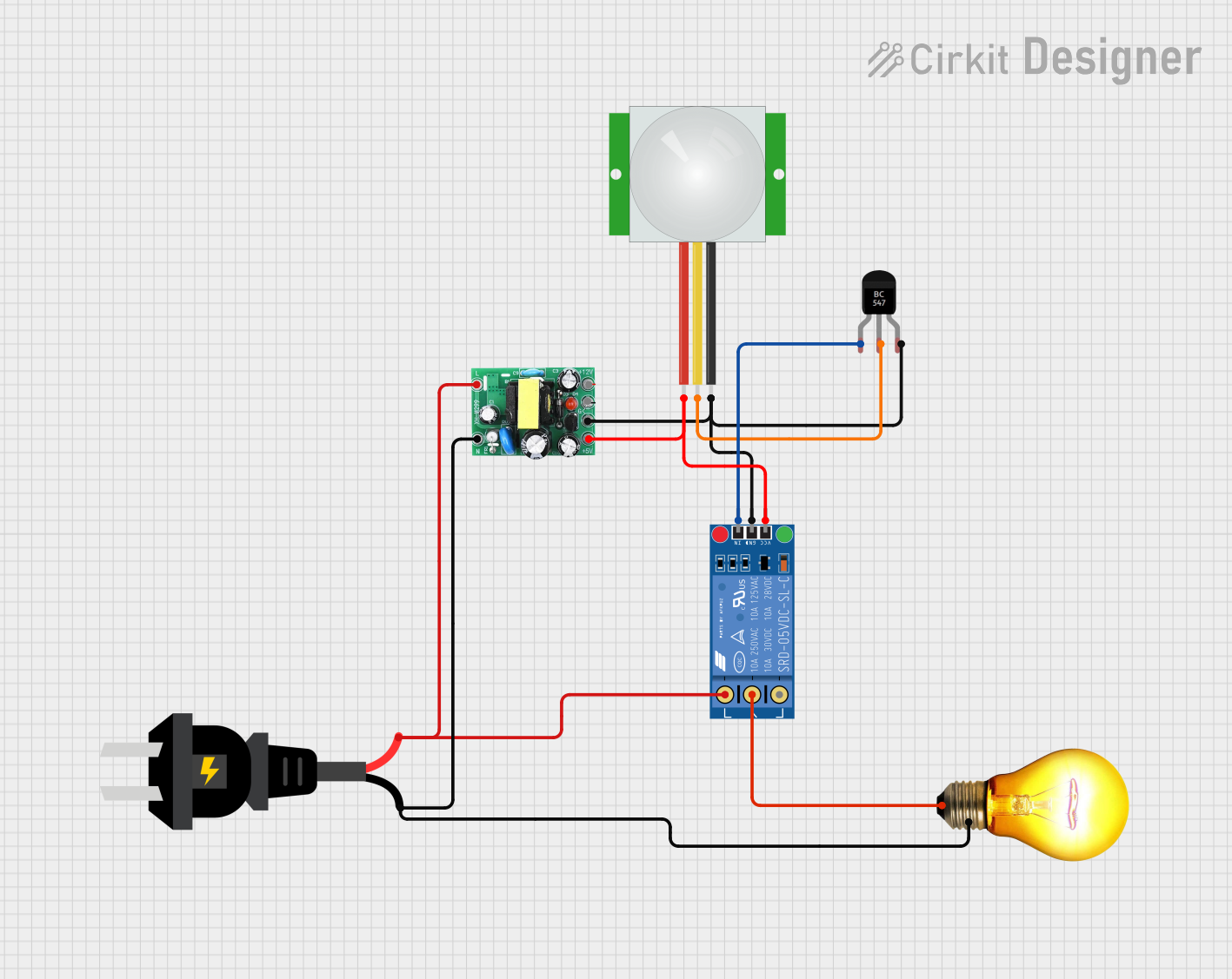
- Control Wiring:
- If using auxiliary contacts, connect them to the control or monitoring system.
- For motorized ACBs, connect the control terminals to the motorized mechanism as per the manufacturer's wiring diagram.
- Testing:
- Perform insulation resistance and continuity tests before energizing the circuit.
- Test the trip mechanism by simulating overload or short-circuit conditions.
Important Considerations and Best Practices
- Always follow the manufacturer's installation and operation manual.
- Ensure proper coordination with upstream and downstream protective devices.
- Regularly inspect and maintain the ACB to ensure reliable operation.
- Avoid exceeding the rated current and breaking capacity of the ACB.
- Use appropriate personal protective equipment (PPE) when working with high-voltage systems.
Example: Connecting an ACB to an Arduino UNO for Monitoring
You can use an Arduino UNO to monitor the status of an ACB via its auxiliary contacts. Below is an example code snippet:
// Define the pin connected to the ACB auxiliary contact
const int acbStatusPin = 2; // Digital pin 2 for status monitoring

void setup() {
  pinMode(acbStatusPin, INPUT_PULLUP); // Configure pin as input with pull-up resistor
  Serial.begin(9600); // Initialize serial communication
}

void loop() {
  int acbStatus = digitalRead(acbStatusPin); // Read the status of the ACB

  if (acbStatus == HIGH) {
    // ACB is in the OFF or tripped state
    Serial.println("ACB is OFF or Tripped");
  } else {
    // ACB is in the ON state
    Serial.println("ACB is ON");
  }

  delay(1000); // Wait for 1 second before checking again
}
Note: Ensure the auxiliary contact voltage is compatible with the Arduino's input voltage (5V). Use an optocoupler or voltage divider if necessary.
Troubleshooting and FAQs
Common Issues Users Might Face
ACB Does Not Trip During Faults:
- Cause: Incorrect trip unit settings or a faulty trip mechanism.
- Solution: Verify and adjust the trip unit settings. Inspect and test the trip mechanism.
Overheating of Terminals:
- Cause: Loose or improper connections.
- Solution: Tighten all connections and ensure proper cable sizing.
Frequent Tripping:
- Cause: Overloaded circuit or short circuit in the load.
- Solution: Reduce the load or locate and fix the short circuit.
Motorized Mechanism Fails to Operate:
- Cause: Faulty control wiring or insufficient power supply.
- Solution: Check the control wiring and ensure the power supply meets the required specifications.
Solutions and Tips for Troubleshooting
- Always isolate the power supply before performing maintenance or troubleshooting.
- Use a multimeter to check for continuity and voltage levels at the terminals.
- Regularly test the ACB's trip mechanism to ensure proper functionality.
- Consult the manufacturer's documentation for detailed troubleshooting steps.
By following this documentation, users can effectively select, install, and maintain an Air Circuit Breaker (ACB) for their electrical systems.