How to Use E Stop: Examples, Pinouts, and Specs
Introduction
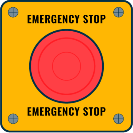
The Emergency Stop (E Stop) is a critical safety component designed to halt the operation of machinery and processes in the event of an emergency. It is a fail-safe mechanism that, when activated, immediately cuts off power to the equipment, thereby helping to prevent accidents, injuries, and damage to the system. E Stops are commonly found in industrial settings, on control panels, and within electronic systems where human safety is a priority.
Explore Projects Built with E Stop


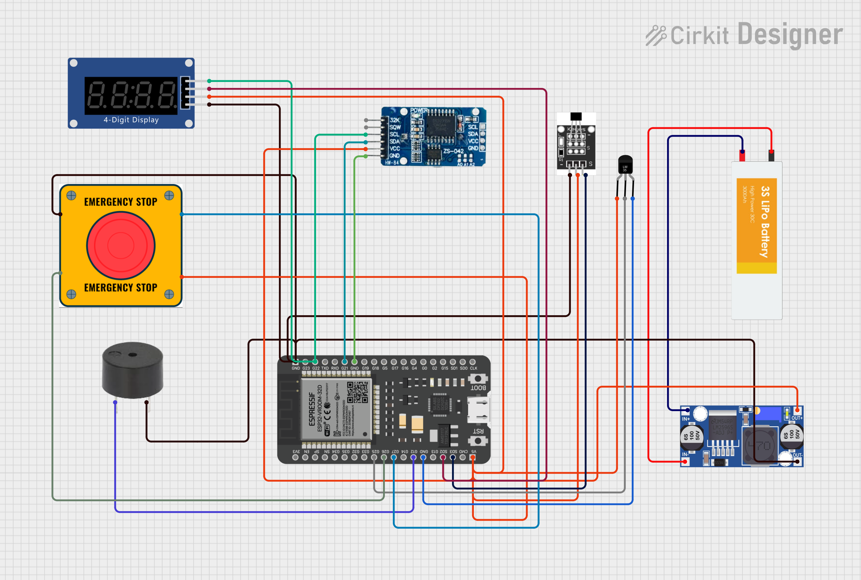

Explore Projects Built with E Stop
Common Applications and Use Cases
- Industrial machinery
- Robotic systems
- Conveyor belts
- Automated production lines
- CNC machines
- Laboratory equipment
Technical Specifications
Key Technical Details
- Voltage Rating: Typically ranges from 24V to 240V AC/DC
- Current Rating: Up to 10A for standard models (higher ratings available)
- Contact Configuration: Normally closed (NC), opens upon actuation
- Durability: Rated for a high number of actuation cycles
Pin Configuration and Descriptions
| Pin Number | Description | Notes |
|---|---|---|
| 1 | Common (COM) | Connect to power supply |
| 2 | Normally Closed (NC) | Connect to the controlled circuit; opens when E Stop is pressed |
| 3 | Normally Open (NO) | Optional; not used in all applications |
Usage Instructions
How to Use the E Stop in a Circuit
Integration: The E Stop should be integrated into the main power or control circuit of the machinery. The NC contacts should be used to ensure that when the E Stop is pressed, the circuit opens and power is cut off.
Wiring: Connect the COM pin to the power supply line. The NC pin should be connected in series with the load (equipment to be controlled).
Mounting: The E Stop should be mounted in an easily accessible location, clearly marked, and unobstructed to ensure quick activation in case of an emergency.
Important Considerations and Best Practices
- Testing: Regularly test the E Stop to ensure it is functioning correctly.
- Visibility: Use a brightly colored actuator (typically red) for the E Stop button.
- Accessibility: Do not place the E Stop where it can be accidentally activated, but ensure it is within easy reach.
- Labeling: Clearly label the E Stop with signage indicating its purpose.
Troubleshooting and FAQs
Common Issues
- E Stop Not Functioning: Ensure that all connections are secure and that the E Stop is not damaged.
- Accidental Activation: If the E Stop is too sensitive or placed in a location where it can be bumped, consider adding a protective collar or relocating the button.
Solutions and Tips for Troubleshooting
- Check Connections: Verify that all wiring is correct and secure.
- Inspect for Damage: Look for any signs of physical damage to the E Stop mechanism.
- Test Regularly: Implement a routine testing procedure to ensure reliability.
FAQs
Q: Can the E Stop be reset after activation? A: Yes, most E Stops are designed to be reset, usually by twisting or pulling the button.
Q: Is the E Stop sufficient for all safety measures? A: While the E Stop is a critical component, it should be part of a comprehensive safety system that includes proper training, guarding, and additional safety devices.
Q: How often should the E Stop be tested? A: It is recommended to test the E Stop before each use of the machinery, or as part of a regular maintenance schedule.
Example Code for Arduino UNO Integration
// Define the E Stop pin
const int eStopPin = 2;

void setup() {
  // Set the E Stop pin as an input
  pinMode(eStopPin, INPUT_PULLUP);
  // Initialize serial communication for debugging
  Serial.begin(9600);
}

void loop() {
  // Check the E Stop state
  int eStopState = digitalRead(eStopPin);

  // If the E Stop is pressed (circuit open), halt the system
  if (eStopState == LOW) {
    // Implement emergency stop procedures
    Serial.println("EMERGENCY STOP ACTIVATED");
    // Add code here to safely halt any connected machinery or processes
    // ...
  }
  // Otherwise, continue normal operation
  else {
    // Normal operation code
    // ...
  }
}
Note: In this example, the E Stop is connected to pin 2 of the Arduino UNO. The INPUT_PULLUP mode is used to enable the internal pull-up resistor, ensuring the pin reads HIGH when the button is not pressed (circuit closed) and LOW when the E Stop is activated (circuit open).