
How to Use DB25: Examples, Pinouts, and Specs
 Design with DB25 in Cirkit Designer
Introduction
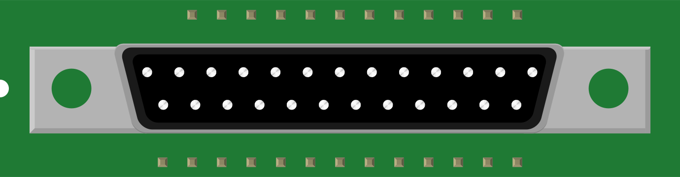
The DB25 is a 25-pin D-subminiature connector widely used for parallel and serial communication. Its robust design and high pin count make it suitable for a variety of applications, including computer peripherals, networking equipment, and industrial control systems. The DB25 connector is available in both male and female configurations and is commonly used in RS-232 serial communication and IEEE 1284 parallel interfaces.
Explore Projects Built with DB25
 Open Project in Cirkit Designer
 Open Project in Cirkit Designer
 Open Project in Cirkit Designer
 Open Project in Cirkit Designer
Explore Projects Built with DB25
Open Project in Cirkit DesignerOpen Project in Cirkit DesignerOpen Project in Cirkit DesignerOpen Project in Cirkit DesignerCommon Applications
- RS-232 serial communication for data transfer between computers and peripherals
- IEEE 1284 parallel communication for printers and scanners
- Industrial control systems and automation
- Networking equipment and legacy hardware connections
Technical Specifications
General Specifications
- Connector Type: D-subminiature, 25-pin
- Pin Count: 25
- Gender: Male or Female (depending on the application)
- Mounting Style: Panel mount or cable mount
- Contact Material: Gold-plated or tin-plated contacts for reliable conductivity
- Housing Material: Metal or plastic shell for durability and shielding
- Current Rating: Typically 5A per pin (varies by manufacturer)
- Voltage Rating: Up to 300V (varies by manufacturer)
- Operating Temperature: -55°C to +105°C (typical range)
Pin Configuration and Descriptions
The pinout of the DB25 connector depends on the specific application. Below are two common configurations: RS-232 serial communication and IEEE 1284 parallel communication.
RS-232 Serial Communication Pinout
| Pin Number | Signal Name | Description |
|---|---|---|
| 1 | Shield Ground | Protective ground for shielding |
| 2 | Transmit Data (TXD) | Data sent from the device |
| 3 | Receive Data (RXD) | Data received by the device |
| 4 | Data Terminal Ready (DTR) | Indicates device is ready |
| 5 | Signal Ground (GND) | Common ground for signals |
| 6 | Data Set Ready (DSR) | Indicates readiness of connected device |
| 7 | Request to Send (RTS) | Request to send data |
| 8 | Clear to Send (CTS) | Clear to send data |
| 9 | Ring Indicator (RI) | Indicates incoming call (modems) |
| 10-25 | Reserved/Unused | Application-specific or not connected |
IEEE 1284 Parallel Communication Pinout
| Pin Number | Signal Name | Description |
|---|---|---|
| 1 | Strobe | Initiates data transfer |
| 2-9 | Data 0-7 | 8-bit parallel data lines |
| 10 | Acknowledge | Indicates data received |
| 11 | Busy | Indicates printer is busy |
| 12 | Paper Out | Indicates paper status |
| 13 | Select | Indicates printer is online |
| 14 | Auto Feed | Controls automatic paper feed |
| 15 | Error | Indicates printer error |
| 16 | Initialize | Resets the printer |
| 17 | Select Input | Selects printer input mode |
| 18-25 | Ground | Signal ground |
Usage Instructions
How to Use the DB25 in a Circuit
- Identify the Application: Determine whether the DB25 will be used for serial or parallel communication.
- Select the Correct Pinout: Refer to the appropriate pin configuration table for your application.
- Connect the Wires: Solder or crimp the wires to the corresponding pins of the DB25 connector. Use a multimeter to verify connections.
- Secure the Connector: If panel mounting, use screws to secure the connector to the panel. For cable mounting, ensure the strain relief is properly installed.
- Test the Connection: Use a continuity tester or communication test software to verify proper operation.
Important Considerations
- Shielding: Use a shielded cable to minimize electromagnetic interference (EMI) in noisy environments.
- Pin Compatibility: Ensure the pinout matches the device or peripheral you are connecting to.
- Voltage and Current Ratings: Do not exceed the specified voltage and current ratings to avoid damage.
- Connector Gender: Verify whether a male or female connector is required for your application.
Example: Connecting DB25 to Arduino UNO for Serial Communication
While the DB25 is not directly compatible with Arduino UNO due to voltage differences, you can use a MAX232 IC to convert RS-232 signals to TTL levels. Below is an example of Arduino code for serial communication:
// Example Arduino code for serial communication with DB25 via MAX232
// Ensure proper wiring between DB25, MAX232, and Arduino UNO

void setup() {
  Serial.begin(9600); // Initialize serial communication at 9600 baud
  Serial.println("DB25 Serial Communication Initialized");
}

void loop() {
  if (Serial.available() > 0) {
    char receivedData = Serial.read(); // Read incoming data
    Serial.print("Received: ");
    Serial.println(receivedData); // Print received data to Serial Monitor
  }
}
Troubleshooting and FAQs
Common Issues
No Communication Between Devices
- Cause: Incorrect pin connections or mismatched pinout.
- Solution: Double-check the pinout and ensure proper wiring.
Signal Interference
- Cause: Lack of shielding in the cable.
- Solution: Use a shielded cable and connect the shield ground (Pin 1).
Overheating or Damage
- Cause: Exceeding voltage or current ratings.
- Solution: Verify the voltage and current requirements of your application.
Loose Connections
- Cause: Poor soldering or crimping.
- Solution: Re-solder or re-crimp the connections securely.
FAQs
Q: Can I use the DB25 for modern devices?
A: While the DB25 is primarily used for legacy devices, it can still be used with modern systems via adapters or converters.
Q: How do I identify the gender of a DB25 connector?
A: A male DB25 connector has pins, while a female DB25 connector has sockets.
Q: Is the DB25 compatible with USB?
A: Not directly. You can use a USB-to-DB25 adapter for compatibility with USB devices.
Q: Can I use all 25 pins simultaneously?
A: Yes, but ensure the total current does not exceed the connector's rating.