How to Use Aux Port: Examples, Pinouts, and Specs
Introduction
The Aux Port, also known as a 3.5mm audio jack, is a widely used connector that facilitates the transmission of audio signals between devices. It is commonly found in smartphones, headphones, car stereos, speakers, and other audio equipment. The Aux Port supports analog audio signals, making it a versatile and straightforward solution for connecting audio devices.
Explore Projects Built with Aux Port


Explore Projects Built with Aux Port
Common Applications and Use Cases
- Connecting smartphones or MP3 players to car stereos or home audio systems.
- Plugging headphones or earphones into audio devices.
- Linking external speakers to laptops, desktops, or other audio sources.
- Bridging audio output from one device to the input of another for recording or playback.
Technical Specifications
The Aux Port is a standardized connector with the following key specifications:
General Specifications
| Parameter | Value/Description |
|---|---|
| Connector Type | 3.5mm TRS (Tip-Ring-Sleeve) or TRRS (Tip-Ring-Ring-Sleeve) |
| Signal Type | Analog audio |
| Number of Conductors | 3 (TRS) or 4 (TRRS) |
| Typical Impedance | 32 ohms (varies based on connected devices) |
| Maximum Voltage | ~2V peak-to-peak (varies by device) |
| Frequency Response | 20 Hz to 20 kHz (audio range) |
Pin Configuration and Descriptions
The Aux Port can have two common configurations: TRS (3 conductors) and TRRS (4 conductors). Below is a breakdown of the pinout:
TRS (Tip-Ring-Sleeve) Configuration
| Pin Name | Position | Description |
|---|---|---|
| Tip | 1 | Left audio channel |
| Ring | 2 | Right audio channel |
| Sleeve | 3 | Ground (common return path) |
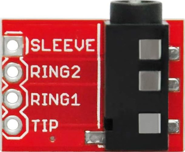
TRRS (Tip-Ring-Ring-Sleeve) Configuration
| Pin Name | Position | Description |
|---|---|---|
| Tip | 1 | Left audio channel |
| Ring 1 | 2 | Right audio channel |
| Ring 2 | 3 | Microphone input (optional, for headsets) |
| Sleeve | 4 | Ground (common return path) |
Usage Instructions
How to Use the Aux Port in a Circuit
- Connecting Devices: Plug a 3.5mm audio cable into the Aux Port of the source device (e.g., smartphone) and the destination device (e.g., speaker or car stereo).
- Signal Transmission: Ensure the cable is securely connected to both devices to avoid signal loss or noise.
- TRRS Compatibility: If using a TRRS connector, ensure the device supports microphone input or other additional features.
Important Considerations and Best Practices
- Cable Quality: Use high-quality, shielded cables to minimize interference and maintain audio fidelity.
- Device Compatibility: Verify that both devices support the same pin configuration (TRS or TRRS).
- Volume Levels: Avoid setting the source device's volume too high to prevent distortion or damage to the destination device.
- Grounding: Ensure proper grounding to avoid hum or noise in the audio signal.
Example: Connecting an Aux Port to an Arduino UNO
While the Aux Port is primarily used for audio, it can also be used to transmit analog signals to an Arduino for basic audio signal processing. Below is an example of reading an audio signal using the Arduino's analog input:
// Example: Reading audio signals from an Aux Port using Arduino UNO
// Connect the Tip (Left channel) of the Aux Port to A0 on the Arduino
// Connect the Sleeve (Ground) of the Aux Port to GND on the Arduino

const int audioPin = A0;  // Analog pin connected to the Aux Port's Tip
int audioValue = 0;       // Variable to store the audio signal value

void setup() {
  Serial.begin(9600);  // Initialize serial communication for debugging
}

void loop() {
  audioValue = analogRead(audioPin);  // Read the audio signal
  Serial.println(audioValue);        // Print the signal value to the Serial Monitor
  delay(10);                         // Small delay for stability
}
Note: The Arduino UNO cannot process audio signals in real-time for playback. This example is for basic signal monitoring or experimentation.
Troubleshooting and FAQs
Common Issues
No Audio Output:
- Ensure the cable is securely connected to both devices.
- Verify that the source device is playing audio and the volume is not muted.
- Check for compatibility between TRS and TRRS configurations.
Static or Noise in the Signal:
- Use a shielded cable to reduce interference.
- Ensure proper grounding of the devices.
- Check for damaged or worn-out cables.
Microphone Not Working (TRRS):
- Confirm that the device supports TRRS connections.
- Use an adapter if the device only supports TRS.
FAQs
Q: Can I use a TRRS cable with a TRS Aux Port?
A: Yes, but the additional conductor (microphone input) will not be utilized, and the connection will function as a standard TRS connection.
Q: What is the difference between TRS and TRRS?
A: TRS has three conductors (Tip, Ring, Sleeve) for stereo audio, while TRRS has four conductors (Tip, Ring, Ring, Sleeve) to support stereo audio and an additional microphone input.
Q: Can I transmit digital audio through an Aux Port?
A: No, the Aux Port is designed for analog audio signals only. For digital audio, use interfaces like USB or HDMI.
Q: Why is there a buzzing sound when using the Aux Port?
A: This could be due to a ground loop issue. Use a ground loop isolator to eliminate the buzzing sound.
By following this documentation, you can effectively use and troubleshoot the Aux Port for various audio applications.