Cirkit Designer
Your all-in-one circuit design IDE
Home /
Component Documentation
How to Use 4 Channel MOSFET Driver: Examples, Pinouts, and Specs
Introduction
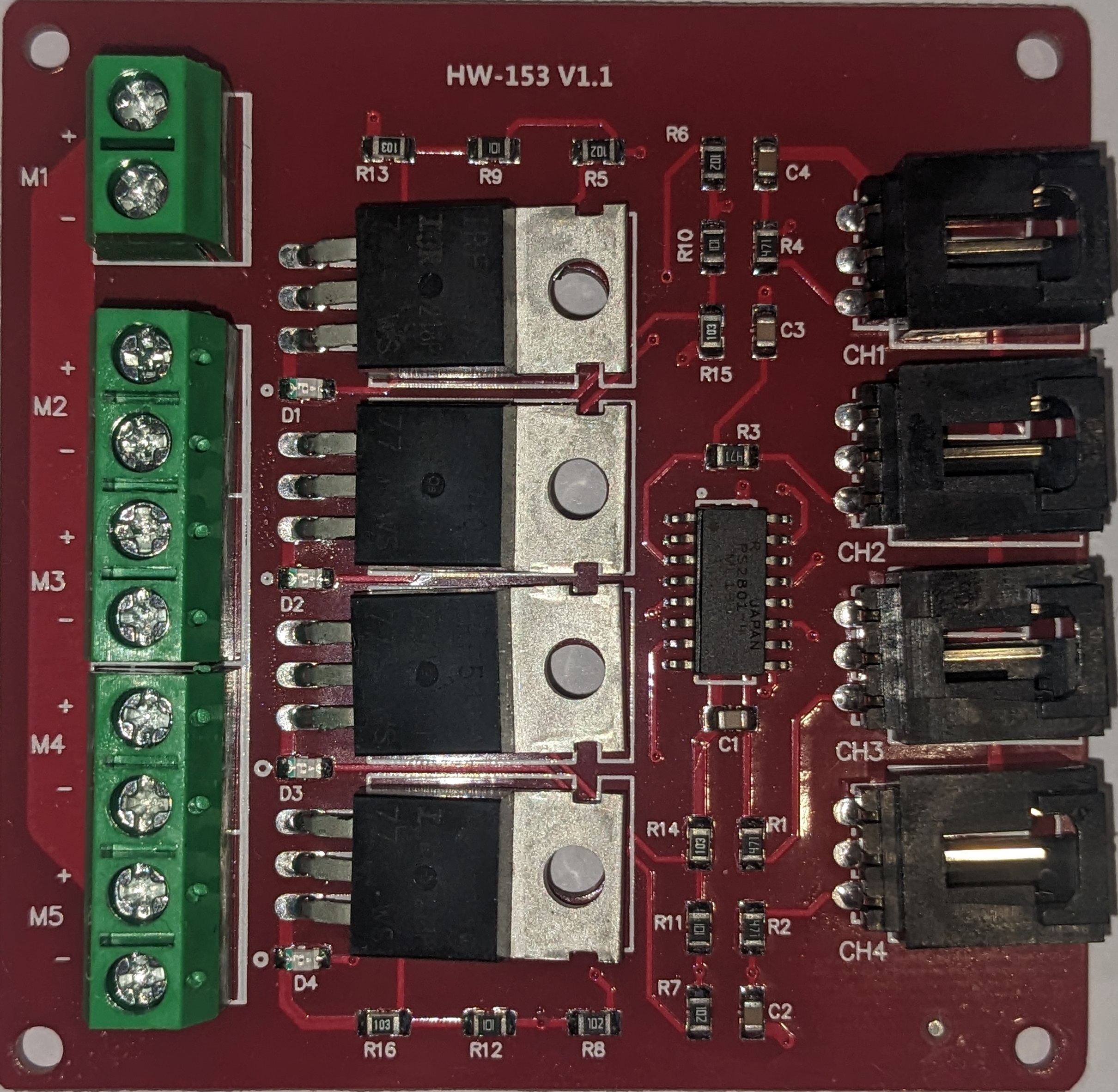
A 4 Channel MOSFET Driver is an electronic device that serves as an interface between a low-power control signal, typically from a microcontroller or logic circuit, and high-power MOSFETs. It is designed to drive four MOSFETs, allowing for precise control over high-current loads in various applications such as DC motor control, LED lighting, power management, and more.
Explore Projects Built with 4 Channel MOSFET Driver
Raspberry Pi and Cytron Motor Driver Controlled 12V Geared Motor System
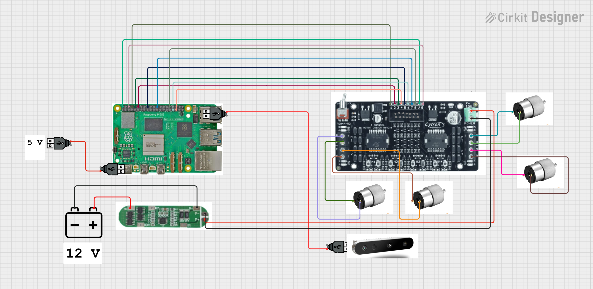
This circuit is designed to control four 12V geared motors using a Raspberry Pi 5 and three Cytron FD04A 4-Channel Motor Drivers. The Raspberry Pi provides direction and speed control signals to the motor drivers, which in turn drive the motors. Power is supplied by a 12V battery managed through a Battery Management System (BMS).
Pixhawk-Controlled Solenoid Driver with Voltage Regulation

This circuit uses an LM393 comparator to drive an IRFZ44N MOSFET based on the comparison between two input signals from a pixhawk 2.4.8 flight controller. The MOSFET switches a solenoid, with a diode for back EMF protection, and the system is powered by a Lipo battery with voltage regulation provided by a step-up boost converter and a step-down voltage regulator to ensure stable operation. A resistor is connected to the gate of the MOSFET for proper biasing.
Arduino UNO Controlled Dual PC Fan System with MOSFET Driver
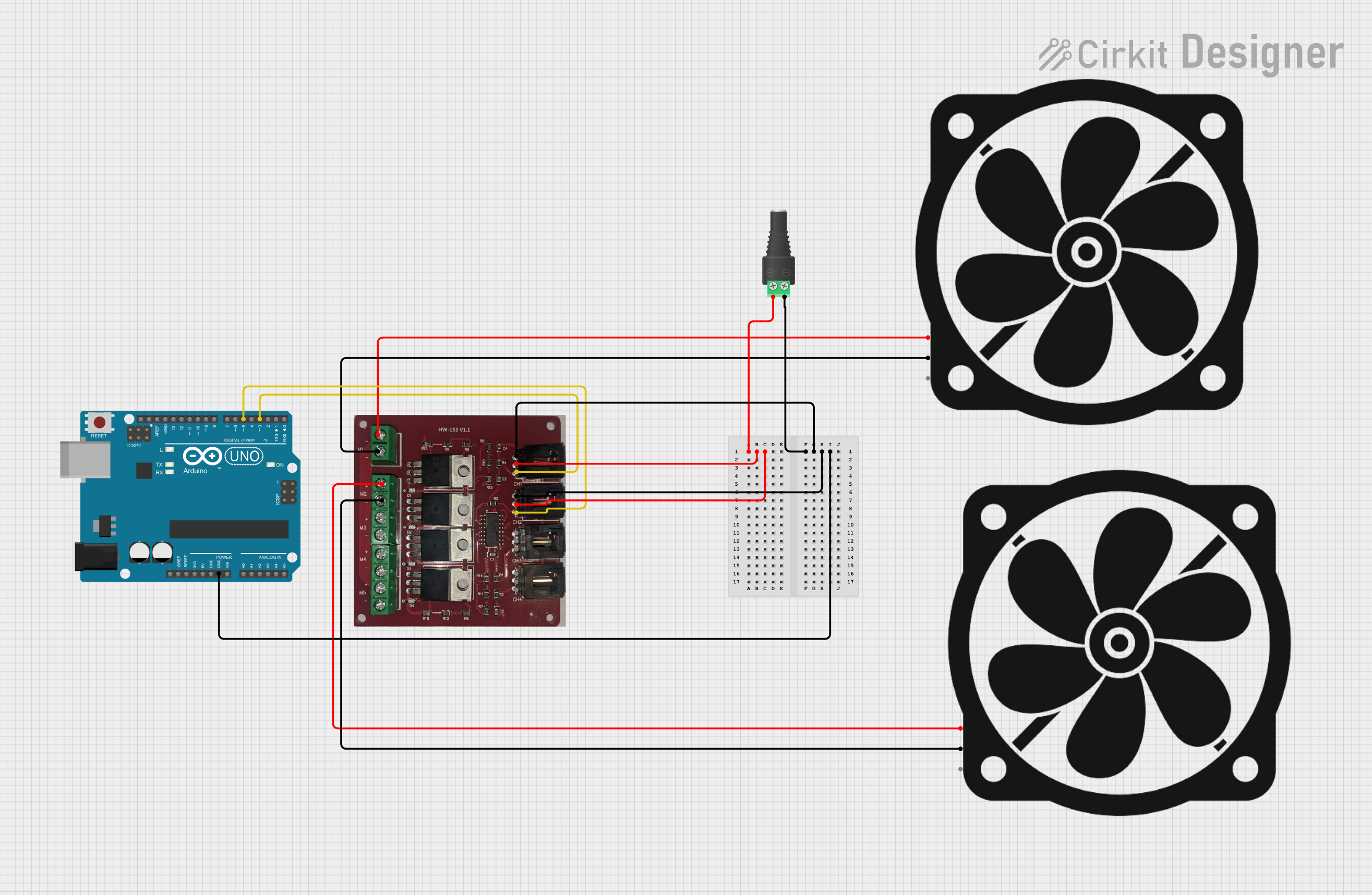
This circuit uses an Arduino UNO to control two PC fans via a 4 Channel MOSFET Driver. The fans are powered through a 2.1mm Barrel Jack with Terminal Block, and the Arduino sends control signals to the MOSFET driver to regulate the fans' operation.
MOSFET-Controlled LED Array Circuit
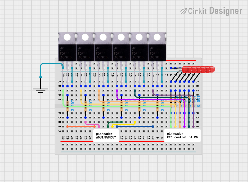
This circuit is designed to control multiple LEDs using MOSFETs as switches. Each MOSFET is connected to a gate resistor for proper biasing and to an LED with a current-limiting resistor in series. The circuit likely functions as a simple LED array driver, where the MOSFETs can be individually controlled to turn the LEDs on and off.
Explore Projects Built with 4 Channel MOSFET Driver
Raspberry Pi and Cytron Motor Driver Controlled 12V Geared Motor System
This circuit is designed to control four 12V geared motors using a Raspberry Pi 5 and three Cytron FD04A 4-Channel Motor Drivers. The Raspberry Pi provides direction and speed control signals to the motor drivers, which in turn drive the motors. Power is supplied by a 12V battery managed through a Battery Management System (BMS).
Pixhawk-Controlled Solenoid Driver with Voltage Regulation
This circuit uses an LM393 comparator to drive an IRFZ44N MOSFET based on the comparison between two input signals from a pixhawk 2.4.8 flight controller. The MOSFET switches a solenoid, with a diode for back EMF protection, and the system is powered by a Lipo battery with voltage regulation provided by a step-up boost converter and a step-down voltage regulator to ensure stable operation. A resistor is connected to the gate of the MOSFET for proper biasing.
Arduino UNO Controlled Dual PC Fan System with MOSFET Driver
This circuit uses an Arduino UNO to control two PC fans via a 4 Channel MOSFET Driver. The fans are powered through a 2.1mm Barrel Jack with Terminal Block, and the Arduino sends control signals to the MOSFET driver to regulate the fans' operation.
MOSFET-Controlled LED Array Circuit
This circuit is designed to control multiple LEDs using MOSFETs as switches. Each MOSFET is connected to a gate resistor for proper biasing and to an LED with a current-limiting resistor in series. The circuit likely functions as a simple LED array driver, where the MOSFETs can be individually controlled to turn the LEDs on and off.
Technical Specifications
Key Technical Details
- Supply Voltage (Vdd): Typically ranges from 4.5V to 18V.
- Input Logic Voltage (Vil/Vih): Compatible with standard logic levels (e.g., 3.3V or 5V).
- Output Current (Iout): Maximum continuous current per channel.
- Switching Frequency: Maximum frequency at which the driver can operate.
- Propagation Delay: Time taken for the input signal to produce an output.
Pin Configuration and Descriptions
| Pin Number | Pin Name | Description |
|---|---|---|
| 1 | IN1 | Input control signal for Channel 1 |
| 2 | OUT1 | Output to MOSFET gate for Channel 1 |
| 3 | IN2 | Input control signal for Channel 2 |
| 4 | OUT2 | Output to MOSFET gate for Channel 2 |
| 5 | IN3 | Input control signal for Channel 3 |
| 6 | OUT3 | Output to MOSFET gate for Channel 3 |
| 7 | IN4 | Input control signal for Channel 4 |
| 8 | OUT4 | Output to MOSFET gate for Channel 4 |
| 9 | Vss | Ground reference for the driver |
| 10 | Vdd | Supply voltage for the driver |
Usage Instructions
How to Use the Component in a Circuit
- Power Supply: Connect the Vdd pin to a suitable power supply, ensuring it matches the driver's voltage requirements.
- Grounding: Connect the Vss pin to the ground of your circuit.
- Input Signals: Connect IN1, IN2, IN3, and IN4 to the control signals. These could be PWM signals from a microcontroller.
- MOSFET Connection: Connect OUT1, OUT2, OUT3, and OUT4 to the gate terminals of your MOSFETs.
- Load Connection: Connect your load (e.g., motor, LED) to the drain of the MOSFETs.
Important Considerations and Best Practices
- Ensure that the input logic voltage is compatible with your control signal source.
- Do not exceed the maximum ratings of voltage and current specified for the driver.
- Use a pull-down resistor on the input pins to prevent floating inputs when no signal is present.
- Implement proper heat dissipation techniques if the driver will be operating at high currents or frequencies.
- Use decoupling capacitors close to the power supply pins to filter out noise and voltage spikes.
Troubleshooting and FAQs
Common Issues
- MOSFETs Not Switching: Check if the input signals are correctly applied and within the specified logic voltage range.
- Overheating: Ensure that the current through the driver does not exceed the maximum rating and that adequate heat sinking is in place.
- Unexpected Behavior: Verify that the power supply is stable and within the specified range. Check for proper grounding.
Solutions and Tips
- If the MOSFETs are not switching, verify the input signal with an oscilloscope or logic analyzer.
- For overheating issues, consider using MOSFETs with lower on-resistance or improving the thermal management of the system.
- In case of unexpected behavior, double-check the wiring and connections, and ensure that there is no short-circuit in the load.
Example Code for Arduino UNO
// Define the control pins for the MOSFET driver
const int controlPin1 = 3; // IN1 on the driver
const int controlPin2 = 5; // IN2 on the driver
const int controlPin3 = 6; // IN3 on the driver
const int controlPin4 = 9; // IN4 on the driver

void setup() {
  // Set the control pins as outputs
  pinMode(controlPin1, OUTPUT);
  pinMode(controlPin2, OUTPUT);
  pinMode(controlPin3, OUTPUT);
  pinMode(controlPin4, OUTPUT);
}

void loop() {
  // Example: Turn on each channel for one second, then off
  digitalWrite(controlPin1, HIGH);
  delay(1000);
  digitalWrite(controlPin1, LOW);

  digitalWrite(controlPin2, HIGH);
  delay(1000);
  digitalWrite(controlPin2, LOW);

  digitalWrite(controlPin3, HIGH);
  delay(1000);
  digitalWrite(controlPin3, LOW);

  digitalWrite(controlPin4, HIGH);
  delay(1000);
  digitalWrite(controlPin4, LOW);
}
This example demonstrates how to control each channel of the MOSFET driver using an Arduino UNO. The control pins are toggled to turn the connected MOSFETs on and off sequentially. Adjust the delay() function to suit the timing requirements of your application.