The TCR1500, manufactured by QW (Part ID: SD), is a precision temperature coefficient resistor designed for high accuracy in temperature sensing applications. This component is engineered to provide stable resistance over a wide temperature range, ensuring reliable performance in circuits requiring precise temperature measurements. Its robust design and high accuracy make it a preferred choice for industrial, automotive, and consumer electronics applications.
Explore Projects Built with tcr1500
Use Cirkit Designer to design, explore, and prototype these projects online. Some projects support real-time simulation. Click "Open Project" to start designing instantly!
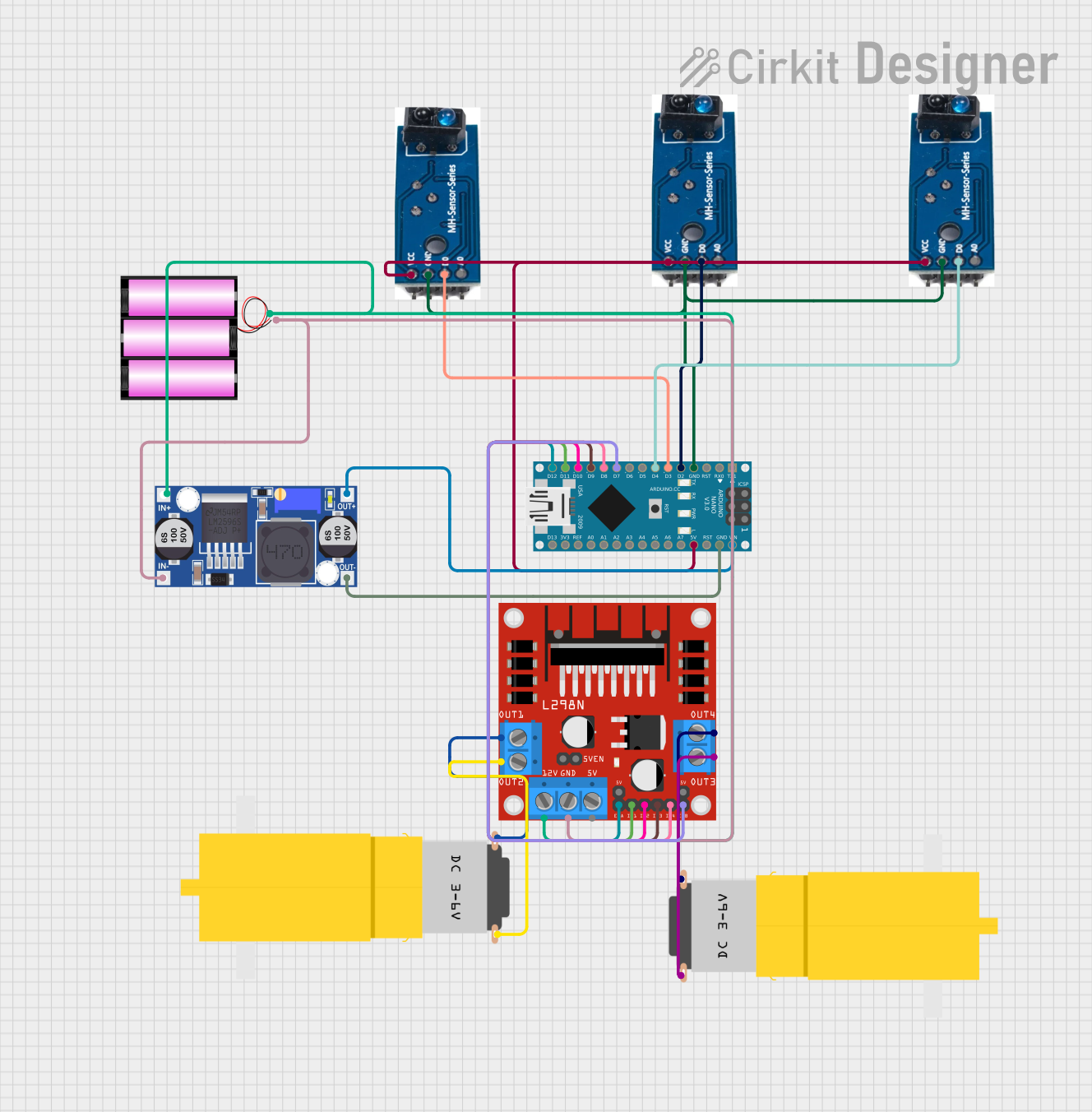
This circuit is a robotic system controlled by an Arduino Nano, which interfaces with three TCRT-5000 IR sensors for obstacle detection and an L298N motor driver to control two DC motors. The system is powered by a 12V battery, regulated by a buck converter to supply the necessary voltage to the Arduino and sensors.
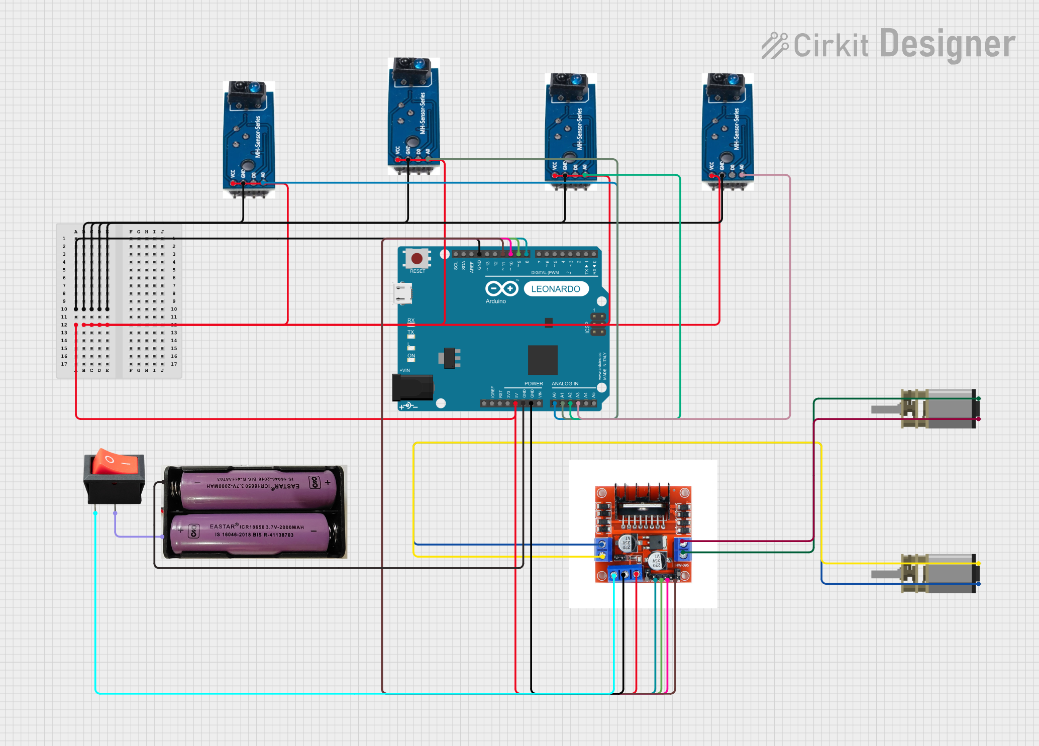
This circuit is a line-following robot that uses four TCRT-5000 IR sensors to detect the path and an Arduino Leonardo to process the sensor data. The Arduino controls two DC motors via an L298N motor driver module, powered by a 7.4V battery and a rocker switch for power control.
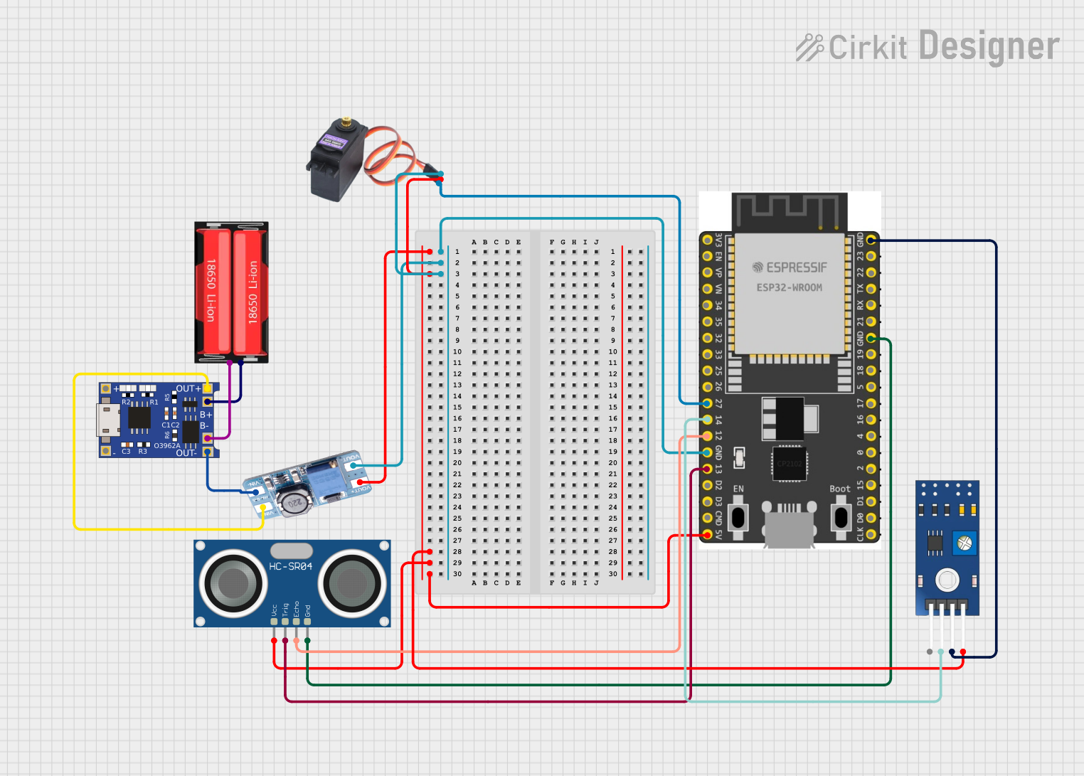
This circuit features a 18650 Li-Ion battery connected to a TP4056 charging module, which in turn is connected to an MT3608 boost converter to step up the voltage. The output of the MT3608 powers an ESP32 microcontroller, a TCRT 5000 IR sensor, an HC-SR04 ultrasonic sensor, and an MG996R servo motor. The ESP32 is configured to control the servo motor via GPIO 27 and to receive input signals from the IR sensor and ultrasonic sensor through GPIO 14 and GPIO 13, respectively.
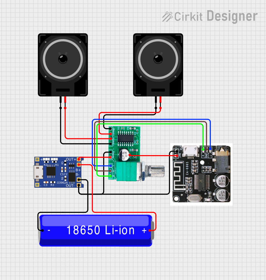
This circuit is a Bluetooth-enabled audio system powered by a rechargeable 18650 Li-ion battery. It includes a TP4056 module for battery charging and protection, a PAM8403 amplifier with volume control to drive two loudspeakers, and a Bluetooth audio receiver to wirelessly receive audio signals.
Stability: Long-term drift < 0.05% per 1,000 hours
Package Type: Axial or SMD (Surface Mount Device)
Pin Configuration and Descriptions
The TCR1500 is a two-terminal resistor. Below is the pin configuration:
Pin Number
Pin Name
Description
1
Terminal 1
Connect to the input side of the circuit
2
Terminal 2
Connect to the output side of the circuit
Usage Instructions
How to Use the TCR1500 in a Circuit
Determine the Resistance Value: Select the appropriate resistance value (e.g., 1 kΩ, 5 kΩ) based on your circuit requirements.
Connect the Terminals:
Terminal 1 should be connected to the input side of the circuit.
Terminal 2 should be connected to the output side or ground, depending on the circuit design.
Ensure Proper Power Rating: Verify that the power dissipation in the resistor does not exceed its rated 0.25 W at 70°C.
Temperature Compensation: Use the TCR1500 in circuits where precise temperature compensation is required, such as Wheatstone bridges or voltage dividers.
Important Considerations and Best Practices
Avoid Overheating: Ensure the resistor operates within its specified temperature range (-55°C to +155°C) to maintain accuracy.
Minimize Noise: Place the resistor away from high-frequency or high-power components to reduce noise interference.
Soldering Precautions: When soldering, use a temperature-controlled soldering iron to avoid thermal damage to the resistor.
Use in Arduino Projects: The TCR1500 can be used in temperature sensing circuits with an Arduino UNO. Below is an example code snippet for reading temperature using the TCR1500 in a voltage divider configuration.
// Example Arduino Code for Reading Temperature with TCR1500
// Assumes TCR1500 is part of a voltage divider circuit connected to A0

const int sensorPin = A0; // Analog pin connected to the voltage divider
float referenceVoltage = 5.0; // Reference voltage of the Arduino
float resistorValue = 10000.0; // Resistance of the fixed resistor in ohms

void setup() {
  Serial.begin(9600); // Initialize serial communication
}

void loop() {
  int sensorValue = analogRead(sensorPin); // Read the analog value
  float voltage = (sensorValue / 1023.0) * referenceVoltage;
  // Calculate the resistance of the TCR1500
  float tcrResistance = (resistorValue * voltage) / (referenceVoltage - voltage);

  // Print the resistance value to the Serial Monitor
  Serial.print("TCR1500 Resistance: ");
  Serial.print(tcrResistance);
  Serial.println(" ohms");

  delay(1000); // Wait for 1 second before the next reading
}
Troubleshooting and FAQs
Common Issues and Solutions
Inaccurate Resistance Readings:
Cause: Operating outside the specified temperature range.
Solution: Ensure the ambient temperature is within -55°C to +155°C.
Overheating:
Cause: Exceeding the power rating of 0.25 W.
Solution: Reduce the current through the resistor or use a resistor with a higher power rating.
Noise in Measurements:
Cause: Placement near high-frequency components.
Solution: Relocate the resistor or use shielding to minimize interference.
Soldering Damage:
Cause: Excessive heat during soldering.
Solution: Use a temperature-controlled soldering iron and limit soldering time.
FAQs
Q1: Can the TCR1500 be used in high-frequency circuits?
A1: While the TCR1500 is primarily designed for precision temperature sensing, it can be used in high-frequency circuits if proper noise reduction techniques are applied.
Q2: What happens if the resistor is exposed to temperatures beyond its operating range?
A2: Exceeding the specified temperature range may result in permanent damage or a significant drift in resistance value.
Q3: Is the TCR1500 available in different resistance values?
A3: Yes, the TCR1500 is available in a range of resistance values from 1 kΩ to 10 kΩ. Check the datasheet for specific part numbers.
Q4: Can I use the TCR1500 with a 3.3V microcontroller?
A4: Yes, the TCR1500 can be used with a 3.3V microcontroller, but ensure the voltage divider circuit is designed accordingly.
By following this documentation, users can effectively integrate the TCR1500 into their projects and achieve precise temperature measurements.


 Open Project in Cirkit Designer