
Cirkit Designer
Your all-in-one circuit design IDE
Home /
Component Documentation
How to Use VARISTOR: Examples, Pinouts, and Specs
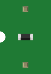
 Design with VARISTOR in Cirkit Designer
Introduction
- A varistor is a voltage-dependent resistor whose resistance decreases as the applied voltage increases. It is primarily used to protect electronic circuits from voltage spikes and surges by clamping excessive voltage to a safe level.
- Common applications include surge protection in power supplies, lightning protection in telecommunications, and transient suppression in automotive electronics.
Explore Projects Built with VARISTOR
Adjustable LM317 Voltage Regulator with ESP32 Control
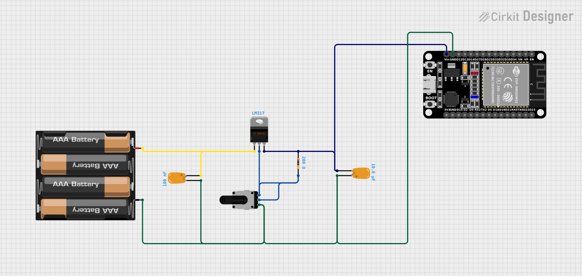
This circuit is a variable voltage power supply featuring an LM317 voltage regulator for adjustable output. It includes an ESP32 microcontroller powered through the regulator, with input and output voltage stabilization provided by tantalum capacitors. A rotary potentiometer is used to set the desired voltage level.
Open Project in Cirkit DesignerAC to DC Power Supply with Voltage Regulation and Overcurrent Protection
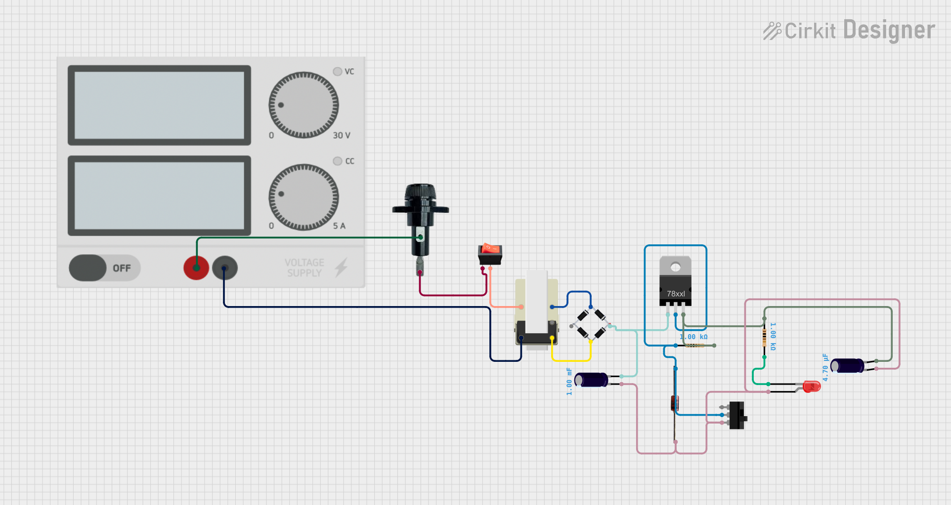
This circuit appears to be a power supply unit with a transformer for stepping down voltage, a bridge rectifier for converting AC to DC, and a voltage regulator for stabilizing the output voltage. It includes a Zener diode for overvoltage protection, capacitors for smoothing out ripples in the DC supply, and a fuse for overcurrent protection. A toggle switch and a rocker switch are used to control the power flow, and there is an LED indicator connected through resistors, likely for power-on indication.
Open Project in Cirkit DesignerAdjustable Voltage Power Supply with LM317 and Digital Voltmeter Display

This is a variable DC power supply circuit that converts AC to a regulated DC output. It uses a transformer for stepping down the voltage, a bridge rectifier for converting AC to DC, and an LM317 voltage regulator with a potentiometer for adjustable output voltage. The circuit includes a voltmeter for displaying the output voltage and an LED as a power indicator.
Open Project in Cirkit DesignerVoltage Regulated Transformer Power Supply Circuit
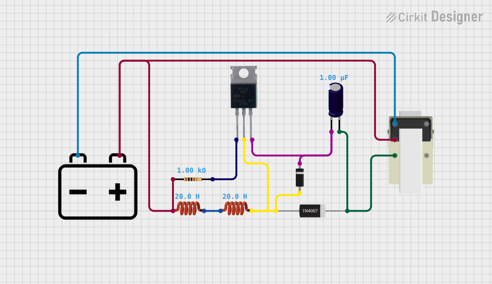
This circuit appears to be a power supply circuit with a transformer connected to a 12V battery for voltage step-up or step-down. It includes a rectification stage with a 1N4007 diode, smoothing with an electrolytic capacitor, and regulation using a Zener diode. Additionally, there are inductors for filtering and a BT139 600 triac for controlling AC power, possibly for dimming or switching applications.
Open Project in Cirkit DesignerExplore Projects Built with VARISTOR
Adjustable LM317 Voltage Regulator with ESP32 Control
This circuit is a variable voltage power supply featuring an LM317 voltage regulator for adjustable output. It includes an ESP32 microcontroller powered through the regulator, with input and output voltage stabilization provided by tantalum capacitors. A rotary potentiometer is used to set the desired voltage level.
Open Project in Cirkit DesignerAC to DC Power Supply with Voltage Regulation and Overcurrent Protection
This circuit appears to be a power supply unit with a transformer for stepping down voltage, a bridge rectifier for converting AC to DC, and a voltage regulator for stabilizing the output voltage. It includes a Zener diode for overvoltage protection, capacitors for smoothing out ripples in the DC supply, and a fuse for overcurrent protection. A toggle switch and a rocker switch are used to control the power flow, and there is an LED indicator connected through resistors, likely for power-on indication.
Open Project in Cirkit DesignerAdjustable Voltage Power Supply with LM317 and Digital Voltmeter Display
This is a variable DC power supply circuit that converts AC to a regulated DC output. It uses a transformer for stepping down the voltage, a bridge rectifier for converting AC to DC, and an LM317 voltage regulator with a potentiometer for adjustable output voltage. The circuit includes a voltmeter for displaying the output voltage and an LED as a power indicator.
Open Project in Cirkit DesignerVoltage Regulated Transformer Power Supply Circuit
This circuit appears to be a power supply circuit with a transformer connected to a 12V battery for voltage step-up or step-down. It includes a rectification stage with a 1N4007 diode, smoothing with an electrolytic capacitor, and regulation using a Zener diode. Additionally, there are inductors for filtering and a BT139 600 triac for controlling AC power, possibly for dimming or switching applications.
Open Project in Cirkit DesignerTechnical Specifications
Key Technical Details:
- Voltage Rating: Typically ranges from 18V to 1,000V (varies by model)
- Energy Absorption: 0.1J to 10,000J (joules)
- Response Time: Less than 25 nanoseconds
- Operating Temperature: -40°C to +85°C (typical)
- Leakage Current: <1mA (at rated voltage)
Pin Configuration and Descriptions: Varistors are typically two-terminal devices. Below is a table describing the pins:
| Pin Number | Name | Description |
|---|---|---|
| 1 | Terminal 1 | Connects to the circuit where voltage protection is required (polarity-independent). |
| 2 | Terminal 2 | Connects to the other side of the circuit (polarity-independent). |
Usage Instructions
How to Use the Component in a Circuit:
- Identify the voltage rating of the varistor that matches the operating voltage of your circuit.
- Connect the varistor in parallel with the load or circuit to be protected. This ensures that when a voltage spike occurs, the varistor will clamp the voltage and divert the excess current away from the load.
- For AC circuits, ensure the varistor's voltage rating exceeds the peak AC voltage.
Important Considerations and Best Practices:
- Always select a varistor with a voltage rating slightly higher than the normal operating voltage of your circuit to avoid premature activation.
- Use a fuse in series with the varistor to protect against catastrophic failure in case of prolonged overvoltage conditions.
- Avoid exposing the varistor to continuous overvoltage, as this can degrade its performance over time.
- For high-energy applications, ensure the varistor's energy absorption rating is sufficient to handle the expected surge energy.
Example: Connecting a Varistor to an Arduino UNO:
- A varistor can be used to protect an Arduino UNO from voltage spikes on its power supply line. Below is an example circuit and code:
Circuit:
- Connect a 14V varistor (e.g., MOV-14D471K) across the 5V and GND pins of the Arduino UNO's power supply input.
Code:
// Example code for Arduino UNO with varistor protection
// This code demonstrates a simple LED blink program.
// The varistor protects the Arduino from voltage spikes on the power supply.

void setup() {
  pinMode(13, OUTPUT); // Set pin 13 as an output for the onboard LED
}

void loop() {
  digitalWrite(13, HIGH); // Turn the LED on
  delay(1000);            // Wait for 1 second
  digitalWrite(13, LOW);  // Turn the LED off
  delay(1000);            // Wait for 1 second
}
Troubleshooting and FAQs
Common Issues:
Varistor Overheating:
- Cause: Continuous overvoltage or excessive energy absorption.
- Solution: Verify the varistor's voltage and energy ratings. Replace with a higher-rated varistor if necessary.
Circuit Not Protected from Spikes:
- Cause: Incorrect varistor placement or insufficient voltage rating.
- Solution: Ensure the varistor is connected in parallel with the load and has an appropriate voltage rating.
Varistor Fails to Clamp Voltage:
- Cause: Degraded varistor due to repeated surges.
- Solution: Replace the varistor and consider adding additional surge protection components.
FAQs:
Can a varistor be used in DC circuits?
- Yes, varistors can be used in both AC and DC circuits. Ensure the voltage rating matches the circuit's operating voltage.
How do I know if a varistor is damaged?
- A damaged varistor may show physical signs like discoloration or cracking. It may also fail to clamp voltage effectively, leading to unprotected circuits.
What happens if I use a varistor with a lower voltage rating than required?
- The varistor may activate prematurely during normal operation, leading to overheating and potential failure.
By following these guidelines, you can effectively use a varistor to protect your electronic circuits from voltage surges and spikes.