
How to Use USB 2.0 Female Module: Examples, Pinouts, and Specs
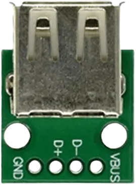
 Design with USB 2.0 Female Module in Cirkit Designer
Introduction
The USB 2.0 Female Module is a versatile connector designed to interface USB devices with electronic circuits. It facilitates both data transfer and power supply, making it an essential component in projects involving microcontrollers, single-board computers, or custom hardware designs. This module is widely used in applications such as USB device communication, charging circuits, and data logging systems.
Common applications include:
- Connecting USB peripherals (e.g., keyboards, mice, flash drives) to embedded systems.
- Powering circuits via USB power (5V).
- Enabling data communication between microcontrollers and computers.
- Prototyping USB-based projects.
Explore Projects Built with USB 2.0 Female Module
 Open Project in Cirkit Designer
 Open Project in Cirkit Designer
 Open Project in Cirkit Designer
 Open Project in Cirkit Designer
Explore Projects Built with USB 2.0 Female Module
Open Project in Cirkit DesignerOpen Project in Cirkit DesignerOpen Project in Cirkit DesignerOpen Project in Cirkit DesignerTechnical Specifications
The USB 2.0 Female Module adheres to the USB 2.0 standard, ensuring compatibility with a wide range of devices. Below are the key technical details:
| Specification | Details |
|---|---|
| Voltage Rating | 5V DC (standard USB power supply) |
| Current Rating | Up to 500mA |
| Data Transfer Rate | Up to 480 Mbps (USB 2.0 standard) |
| Connector Type | USB Type-A Female |
| Dimensions | Varies by module, typically compact |
| Operating Temperature | -20°C to 70°C |
Pin Configuration and Descriptions
The USB 2.0 Female Module typically has four pins, as described in the table below:
| Pin Number | Name | Description |
|---|---|---|
| 1 | VCC | Power supply pin (5V DC) |
| 2 | D- | Data line for differential signaling (negative) |
| 3 | D+ | Data line for differential signaling (positive) |
| 4 | GND | Ground pin |
Usage Instructions
How to Use the USB 2.0 Female Module in a Circuit
- Power Supply: Connect the VCC pin to a 5V power source and the GND pin to the circuit ground. This will provide power to the connected USB device.
- Data Communication: Connect the D+ and D- pins to the corresponding data lines of your microcontroller or USB interface IC. Ensure proper impedance matching for reliable data transfer.
- Mounting: Secure the module to your PCB or breadboard using soldering or connectors, depending on the module design.
Important Considerations and Best Practices
- Voltage Regulation: Ensure that the connected circuit can handle the 5V power supplied by the USB module. Use a voltage regulator if your circuit operates at a lower voltage.
- Data Line Protection: Add pull-up or pull-down resistors on the data lines as required by your microcontroller or USB interface IC.
- Avoid Overloading: Do not exceed the 500mA current rating to prevent damage to the USB port or module.
- Cable Quality: Use high-quality USB cables to minimize signal degradation during data transfer.
Example: Connecting to an Arduino UNO
The USB 2.0 Female Module can be used to interface USB devices with an Arduino UNO. Below is an example of how to connect and use the module:
Circuit Connections
- Connect the VCC pin of the module to the 5V pin on the Arduino.
- Connect the GND pin of the module to the GND pin on the Arduino.
- Connect the D+ and D- pins to the appropriate digital pins on the Arduino for data communication.
Sample Code
/* Example code for reading data from a USB device connected to the USB 2.0
   Female Module. This example assumes the USB device is a serial device. */

#include <SoftwareSerial.h>

// Define the pins for D+ and D- connections
#define RX_PIN 10  // Connect to D+ of the USB module
#define TX_PIN 11  // Connect to D- of the USB module

// Initialize SoftwareSerial for USB communication
SoftwareSerial usbSerial(RX_PIN, TX_PIN);

void setup() {
  // Start the serial communication with the USB device
  usbSerial.begin(9600);
  Serial.begin(9600); // For debugging via the Arduino Serial Monitor
  Serial.println("USB 2.0 Female Module Example");
}

void loop() {
  // Check if data is available from the USB device
  if (usbSerial.available()) {
    // Read data from the USB device
    char data = usbSerial.read();
    // Print the received data to the Serial Monitor
    Serial.print("Received: ");
    Serial.println(data);
  }
}
Troubleshooting and FAQs
Common Issues
No Power to the USB Device
- Cause: Incorrect connection of the VCC or GND pins.
- Solution: Verify the connections and ensure the power source provides 5V.
Data Transfer Fails
- Cause: Improper connection of D+ and D- pins or poor-quality USB cable.
- Solution: Check the wiring and use a high-quality USB cable. Ensure proper pull-up or pull-down resistors are used if required.
Overheating
- Cause: Excessive current draw by the connected USB device.
- Solution: Ensure the device does not exceed the 500mA current rating. Use a powered USB hub if necessary.
FAQs
Can this module be used with USB 3.0 devices?
- Yes, USB 3.0 devices are backward compatible with USB 2.0, but the data transfer rate will be limited to 480 Mbps.
Is additional circuitry required for data communication?
- It depends on your application. For basic power supply, no additional circuitry is needed. For data communication, you may need pull-up resistors or a USB interface IC.
Can I use this module to charge devices?
- Yes, the module can supply 5V power to charge devices, provided the current draw does not exceed 500mA.
By following this documentation, you can effectively integrate the USB 2.0 Female Module into your projects for reliable power and data transfer.