How to Use keystudio motion sensor: Examples, Pinouts, and Specs
Introduction
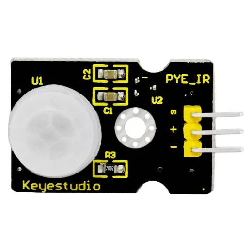
The Keyestudio Motion Sensor is an electronic device that detects motion within its vicinity. It is commonly used in security systems, lighting control, and automation projects. The sensor is often employed in hobbyist projects, particularly those involving Arduino microcontrollers, due to its ease of use and integration capabilities.
Explore Projects Built with keystudio motion sensor
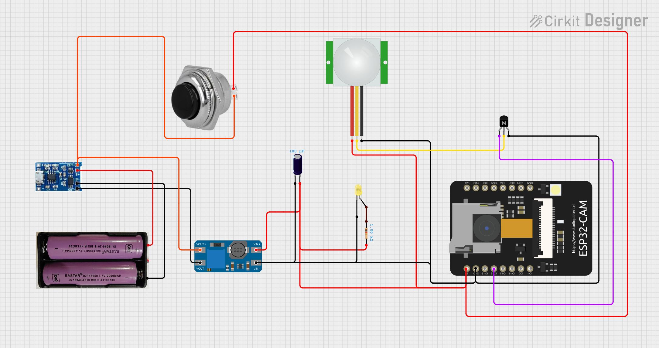
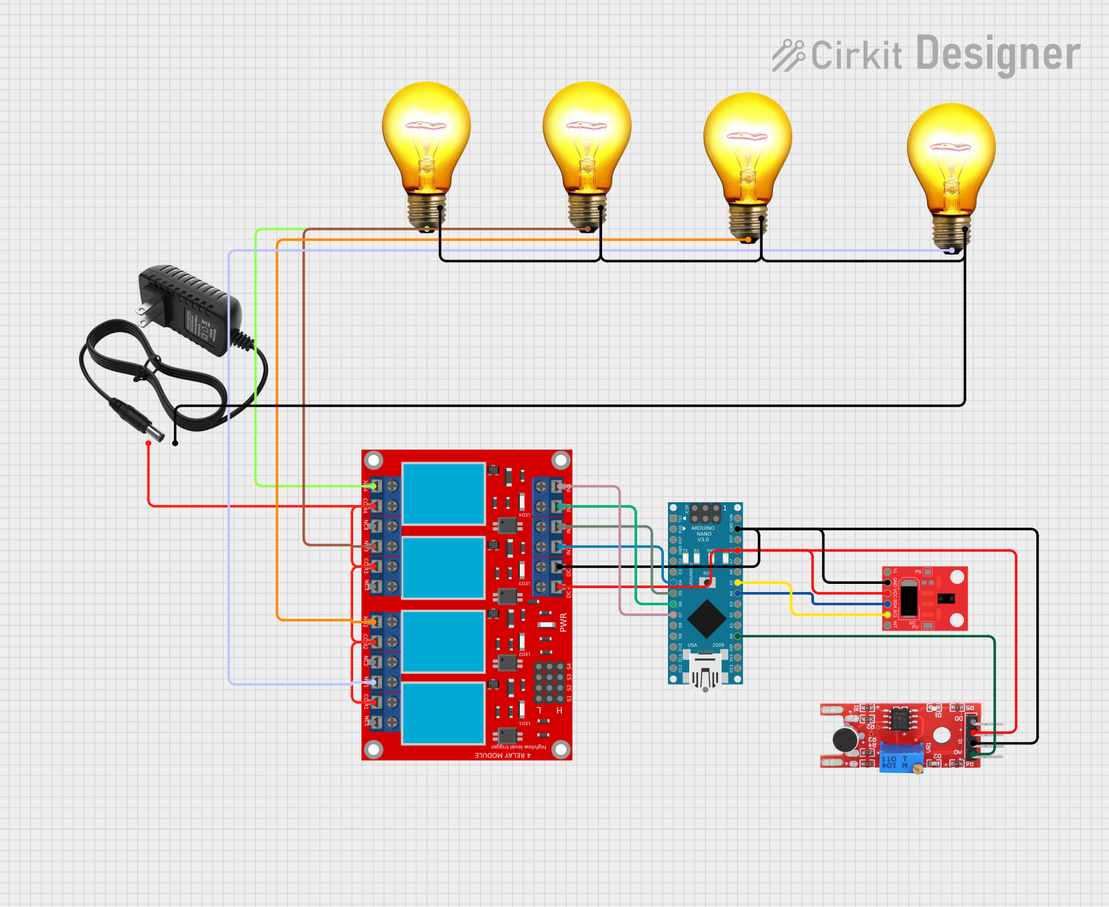
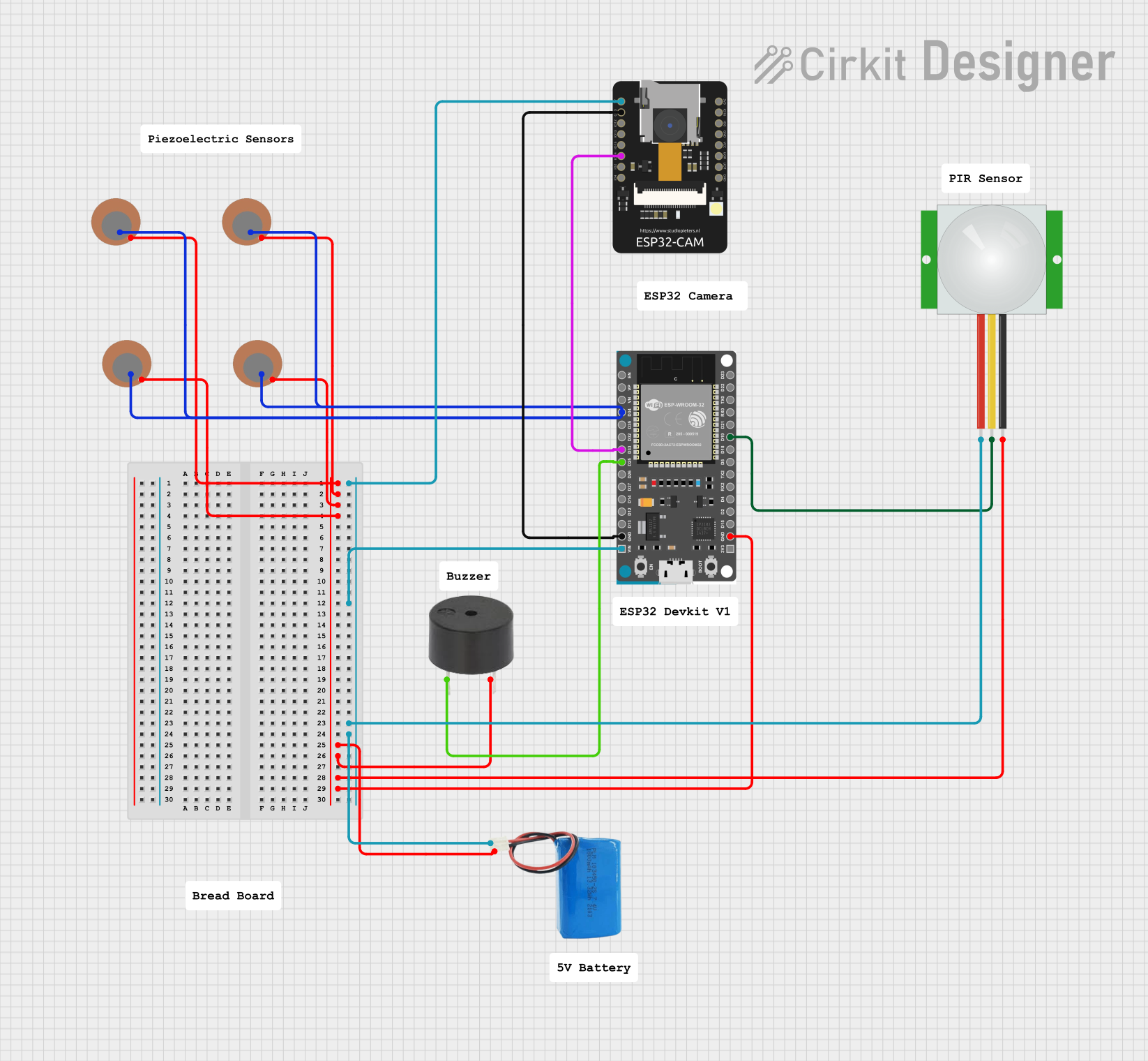
Explore Projects Built with keystudio motion sensor
Technical Specifications
Key Technical Details
- Operating Voltage: 4.5V to 20V
- Current Draw: <50uA (idle), 15mA (during detection)
- Detection Range: Up to 7 meters (adjustable)
- Detection Angle: <140 degrees
- Output Type: Digital (High/Low signal)
- Delay Time: Adjustable (0.3 seconds to 5 minutes)
- Operating Temperature: -20°C to +80°C
Pin Configuration and Descriptions
| Pin Number | Name | Description |
|---|---|---|
| 1 | VCC | Power supply input (4.5V to 20V) |
| 2 | OUT | Digital output signal (High/Low) |
| 3 | GND | Ground connection |
Usage Instructions
Integration with a Circuit
- Power Supply: Connect the VCC pin to a power supply within the 4.5V to 20V range.
- Output Signal: Connect the OUT pin to a digital input pin on your microcontroller.
- Grounding: Connect the GND pin to the ground of your power supply and microcontroller.
Important Considerations and Best Practices
- Ensure that the power supply voltage does not exceed the maximum rating of 20V.
- Avoid placing the sensor in an environment with rapid temperature changes to prevent false triggers.
- Adjust the delay time and sensitivity knobs on the sensor to fine-tune its performance for your specific application.
- Use pull-up or pull-down resistors on the output pin if necessary, depending on your microcontroller's input configuration.
Example Code for Arduino UNO
// Define the motion sensor pin
const int motionSensorPin = 2; // Connect the OUT pin of the sensor to digital pin 2

// Variable to hold the motion sensor status
int motionStatus = 0;

void setup() {
  // Set the motion sensor pin as an input
  pinMode(motionSensorPin, INPUT);

  // Begin serial communication at a baud rate of 9600
  Serial.begin(9600);
}

void loop() {
  // Read the status of the motion sensor
  motionStatus = digitalRead(motionSensorPin);

  // Check if motion was detected
  if (motionStatus == HIGH) {
    // Motion detected
    Serial.println("Motion detected!");
    // Add your code here to handle the motion detection event
  } else {
    // No motion detected
    Serial.println("No motion detected.");
  }

  // Delay for a short period to avoid spamming the serial output
  delay(100);
}
Troubleshooting and FAQs
Common Issues
- Sensor not detecting motion: Ensure that the sensor is properly powered and that the sensitivity is correctly adjusted.
- False triggers: Adjust the delay time to avoid false detections and ensure the sensor is not facing a heat source or window.
- No output signal: Check the wiring and connections, and ensure that the microcontroller's input pin is configured correctly.
Solutions and Tips for Troubleshooting
- Double-check all connections and ensure that the sensor is not subjected to electrical noise.
- If using long wires, consider using shielded cables to minimize interference.
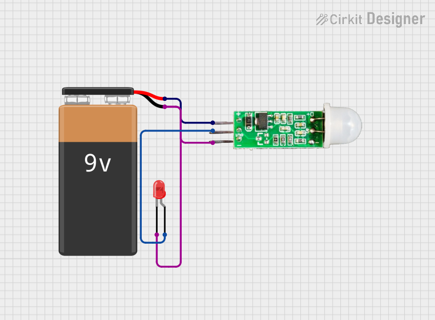
- Test the sensor with a simple LED circuit to confirm its operation before integrating it with a microcontroller.
FAQs
Q: Can the sensor be used outdoors? A: The sensor can be used outdoors but should be protected from direct sunlight and water.
Q: How can I adjust the range and delay of the sensor? A: The sensor typically has two potentiometers to adjust the sensitivity (range) and the time delay.
Q: What is the output voltage of the OUT pin when motion is detected? A: The output voltage is typically equal to the VCC supply voltage when motion is detected.
Remember to always follow safety guidelines when working with electronic components and consult the sensor's datasheet for more detailed information.