
How to Use ST7920: Examples, Pinouts, and Specs
 Design with ST7920 in Cirkit Designer
Introduction
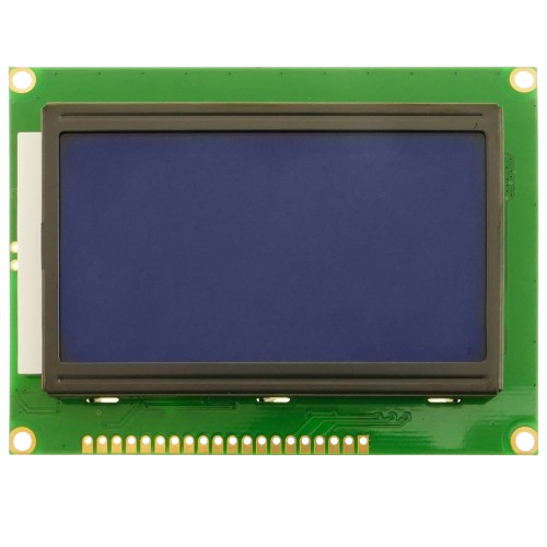
The ST7920 is a versatile graphic LCD controller and driver designed to support a wide range of display formats. It is widely used in embedded systems for displaying both text and graphics, making it a popular choice for applications such as industrial control panels, consumer electronics, and DIY projects. The ST7920 features a built-in character generator, which simplifies the process of displaying text, and it can interface with microcontrollers using either parallel or serial communication.
Explore Projects Built with ST7920
 Open Project in Cirkit Designer
 Open Project in Cirkit Designer
 Open Project in Cirkit Designer
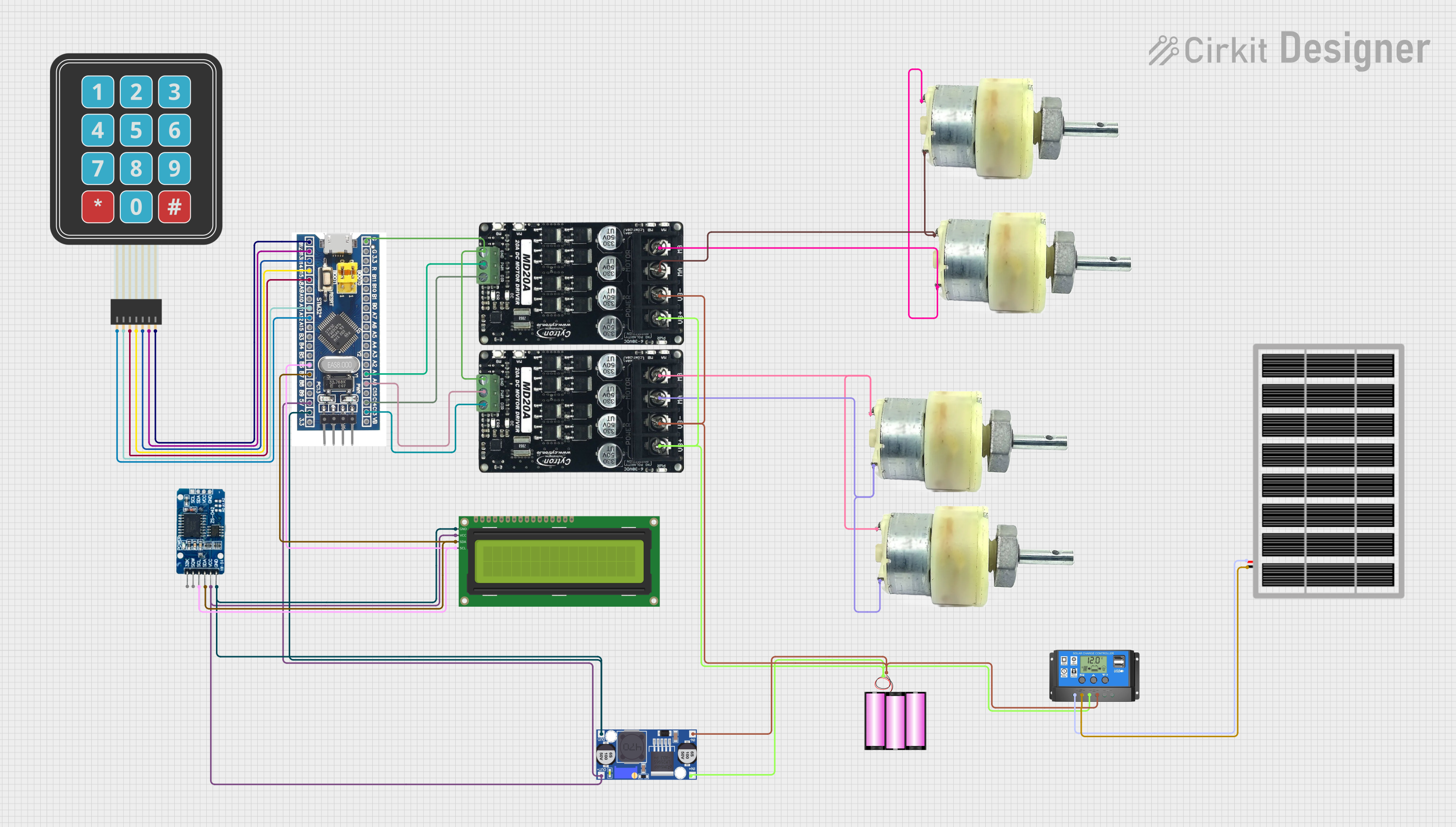
 Open Project in Cirkit Designer
Explore Projects Built with ST7920

 Open Project in Cirkit Designer
 Open Project in Cirkit Designer
 Open Project in Cirkit Designer
 Open Project in Cirkit Designer
Technical Specifications
The ST7920 is designed to work with graphic LCDs and offers the following key specifications:
Key Technical Details
- Operating Voltage: 4.5V to 5.5V
- Logic Voltage Levels: Compatible with 5V logic
- Communication Interfaces: 8-bit/4-bit parallel or SPI (serial)
- Display Resolution: Supports up to 128x64 pixels
- Built-in Character Generator: 8x16 and 16x16 font support
- Operating Temperature: -20°C to +70°C
- Power Consumption: Low power consumption for embedded applications
Pin Configuration and Descriptions
The ST7920 typically interfaces with a microcontroller through a set of pins. Below is the pin configuration:
| Pin | Name | Description |
|---|---|---|
| 1 | VSS | Ground (0V) connection |
| 2 | VDD | Power supply (4.5V to 5.5V) |
| 3 | VO | Contrast adjustment input (connect to a potentiometer for contrast control) |
| 4 | RS | Register Select: 0 = Command, 1 = Data |
| 5 | R/W | Read/Write: 0 = Write, 1 = Read |
| 6 | E | Enable signal for data transfer |
| 7-14 | DB0-DB7 | Data bus lines (used in 8-bit parallel mode; DB4-DB7 used in 4-bit mode) |
| 15 | PSB | Interface mode select: 0 = Serial (SPI), 1 = Parallel |
| 16 | NC | No connection (not used) |
| 17 | RST | Reset pin (active low) |
| 18 | BLA | Backlight anode (connect to +5V through a resistor) |
| 19 | BLK | Backlight cathode (connect to ground) |
Usage Instructions
The ST7920 can be used in either parallel or serial mode, depending on the application requirements. Below are the steps and considerations for using the ST7920 in a circuit:
Connecting the ST7920 to a Microcontroller
- Power Supply: Connect the VDD pin to a 5V power source and the VSS pin to ground.
- Contrast Adjustment: Connect the VO pin to the wiper of a 10kΩ potentiometer. Connect one end of the potentiometer to VDD and the other to VSS.
- Interface Mode: Set the PSB pin to 0 for SPI (serial) mode or 1 for parallel mode.
- Data Lines:
- For parallel mode, connect DB0-DB7 (or DB4-DB7 for 4-bit mode) to the microcontroller.
- For serial mode, connect only the RS, R/W, and E pins, along with the serial data line.
- Backlight: Connect the BLA pin to 5V through a current-limiting resistor (e.g., 220Ω) and the BLK pin to ground.
Example: Using the ST7920 with Arduino UNO (SPI Mode)
Below is an example of how to connect and program the ST7920 in SPI mode with an Arduino UNO:
Wiring Diagram
| ST7920 Pin | Arduino Pin |
|---|---|
| VSS | GND |
| VDD | 5V |
| VO | Potentiometer |
| PSB | GND (SPI mode) |
| RS | D8 |
| R/W | GND |
| E | D9 |
| BLA | 5V (via 220Ω) |
| BLK | GND |
Arduino Code
#include <U8glib.h> // Include the U8glib library for ST7920 support

// Initialize the ST7920 in SPI mode (RS = D8, E = D9)
U8GLIB_ST7920_128X64 u8g(8, 9, U8G_PIN_NONE);

void setup() {
  // Begin communication with the display
  u8g.setRot180(); // Rotate display if needed (optional)
}

void loop() {
  // Start the display update process
  u8g.firstPage();
  do {
    drawGraphics(); // Call the function to draw on the display
  } while (u8g.nextPage());

  delay(1000); // Update every second
}

void drawGraphics() {
  // Draw text and graphics on the display
  u8g.setFont(u8g_font_6x10); // Set font
  u8g.drawStr(0, 10, "Hello, ST7920!"); // Display text
  u8g.drawBox(10, 20, 50, 30); // Draw a filled rectangle
  u8g.drawCircle(80, 40, 10); // Draw a circle
}
Best Practices
- Use decoupling capacitors (e.g., 0.1µF) near the VDD and VSS pins to reduce noise.
- Ensure proper contrast adjustment using the VO pin and a potentiometer.
- Avoid leaving unused pins floating; connect them to ground or VDD as specified in the datasheet.
- For SPI mode, ensure the PSB pin is tied to ground.
Troubleshooting and FAQs
Common Issues
No Display Output:
- Verify the power supply connections (VDD and VSS).
- Check the contrast adjustment (VO pin).
- Ensure the backlight (BLA and BLK) is properly connected.
Corrupted or Incomplete Graphics:
- Check the communication mode (PSB pin) and wiring.
- Ensure the microcontroller's SPI or parallel pins are correctly configured.
Display Flickering:
- Add decoupling capacitors near the power pins.
- Verify the current-limiting resistor for the backlight.
FAQs
Q: Can the ST7920 work with 3.3V microcontrollers?
A: The ST7920 is designed for 5V logic. Use level shifters to interface with 3.3V microcontrollers.
Q: How do I switch between parallel and serial modes?
A: Set the PSB pin to 1 for parallel mode or 0 for serial (SPI) mode.
Q: What library should I use with Arduino?
A: The U8glib library is a popular choice for working with the ST7920.
By following this documentation, you can effectively integrate the ST7920 into your projects and troubleshoot common issues.