How to Use 5v Adapter Board: Examples, Pinouts, and Specs
Introduction
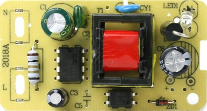
The 5V Adapter Board (Manufacturer Part ID: 5v_Adapter_Board) is a compact circuit board designed to convert AC mains voltage into a stable 5V DC output. This component is widely used to power low-voltage electronic devices, including microcontrollers, sensors, and other peripherals. Its small form factor and reliable performance make it an essential component in prototyping, DIY electronics, and embedded systems.
Explore Projects Built with 5v Adapter Board


Explore Projects Built with 5v Adapter Board
Common Applications and Use Cases
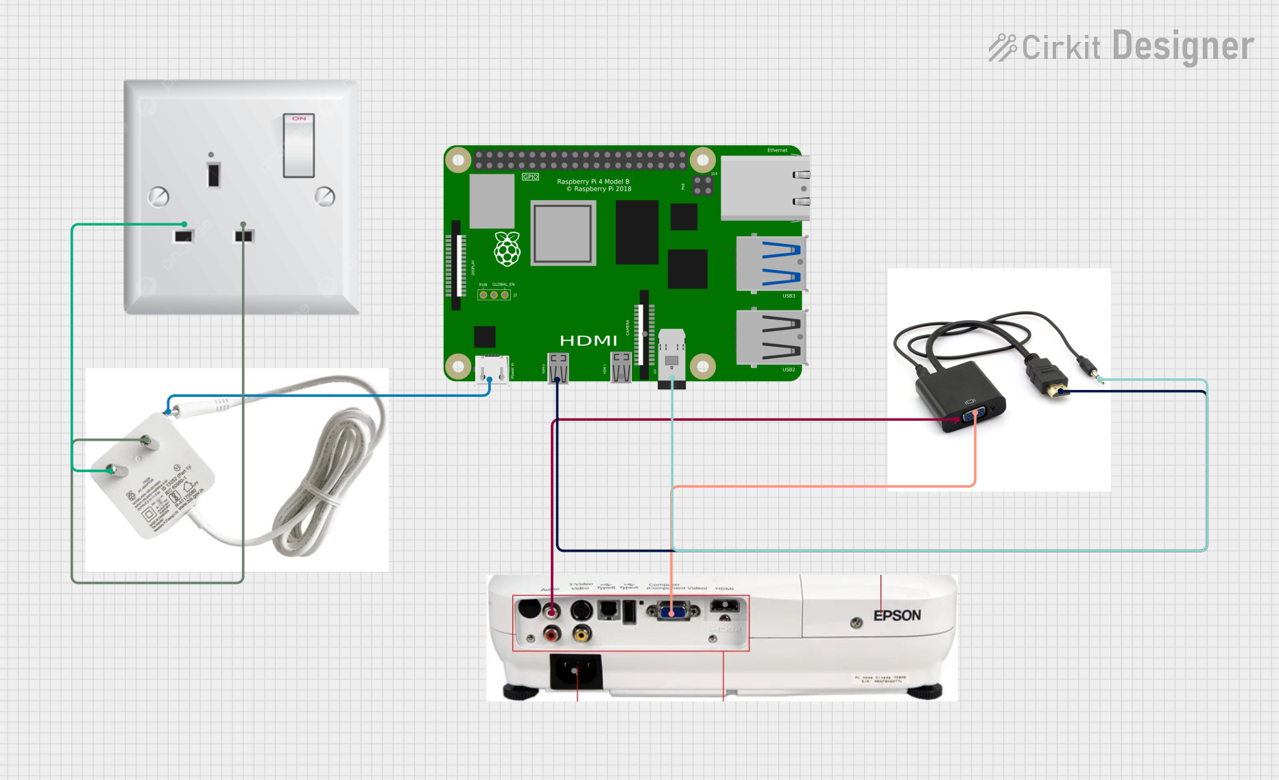
- Powering microcontrollers such as Arduino, Raspberry Pi, and ESP32.
- Supplying 5V DC to sensors, relays, and other low-power devices.
- Providing a stable power source for breadboard-based projects.
- Used in IoT devices, home automation systems, and small robotics.
Technical Specifications
The following table outlines the key technical details of the 5V Adapter Board:
| Parameter | Value |
|---|---|
| Input Voltage | 100-240V AC (50/60Hz) |
| Output Voltage | 5V DC |
| Output Current | Up to 1A |
| Power Rating | 5W |
| Efficiency | ≥ 75% |
| Dimensions | Varies by manufacturer (e.g., 25mm x 20mm) |
| Operating Temperature | -20°C to +60°C |
| Safety Features | Over-voltage, over-current, and short-circuit protection |
Pin Configuration and Descriptions
The 5V Adapter Board typically has the following pin configuration:
| Pin Name | Description |
|---|---|
| AC IN (L) | Live wire input for AC mains voltage. |
| AC IN (N) | Neutral wire input for AC mains voltage. |
| GND | Ground connection for the DC output. |
| +5V | Positive 5V DC output. |
Note: Always verify the pin configuration on your specific board, as it may vary slightly depending on the manufacturer.
Usage Instructions
How to Use the 5V Adapter Board in a Circuit
Connect the AC Input:
- Identify the
AC IN (L)andAC IN (N)pins on the board. - Connect the live and neutral wires from the AC mains supply to these pins. Ensure proper insulation and safety precautions when handling AC voltage.
- Identify the
Connect the DC Output:
- Use the
+5VandGNDpins to supply power to your circuit or device. - Verify the polarity of the connections to avoid damage to your components.
- Use the
Power On:
- Once all connections are secure, plug in the AC mains supply. The board will convert the AC voltage to a stable 5V DC output.
Important Considerations and Best Practices
- Safety First: Always handle the AC input connections with care. Ensure the board is properly insulated and mounted in a safe enclosure to prevent accidental contact with live wires.
- Load Capacity: Do not exceed the maximum output current (1A) to avoid overheating or damaging the board.
- Ventilation: Ensure adequate ventilation around the board to prevent overheating, especially during prolonged use.
- Testing: Use a multimeter to verify the output voltage before connecting sensitive devices.
Example: Using the 5V Adapter Board with an Arduino UNO
The 5V Adapter Board can be used to power an Arduino UNO. Follow these steps:
- Connect the
+5Vpin of the adapter board to the5Vpin on the Arduino UNO. - Connect the
GNDpin of the adapter board to theGNDpin on the Arduino UNO. - Plug in the AC mains supply to the adapter board.
Here is a simple Arduino sketch to blink an LED while powered by the 5V Adapter Board:
// This sketch blinks an LED connected to pin 13 of the Arduino UNO.
// Ensure the Arduino is powered by the 5V Adapter Board.

void setup() {
  pinMode(13, OUTPUT); // Set pin 13 as an output pin
}

void loop() {
  digitalWrite(13, HIGH); // Turn the LED on
  delay(1000);            // Wait for 1 second
  digitalWrite(13, LOW);  // Turn the LED off
  delay(1000);            // Wait for 1 second
}
Warning: Always double-check the connections before powering the circuit to avoid damage to the Arduino or other components.
Troubleshooting and FAQs
Common Issues and Solutions
| Issue | Possible Cause | Solution |
|---|---|---|
| No output voltage | Incorrect AC input connection | Verify the AC IN (L) and AC IN (N) connections. |
| Output voltage is unstable | Overloading the board | Ensure the connected load does not exceed 1A. |
| Board overheats | Insufficient ventilation or overloading | Provide proper ventilation and reduce the load. |
| Device connected to the board is not working | Incorrect polarity or loose connections | Check the +5V and GND connections for proper polarity and secure wiring. |
FAQs
Can I use the 5V Adapter Board to power a Raspberry Pi?
- Yes, but ensure the board can supply sufficient current (at least 1A) for your Raspberry Pi model.
Is the board safe to use with AC mains voltage?
- Yes, the board is designed for AC mains voltage. However, always follow safety precautions and use proper insulation.
Can I use this board outdoors?
- The board is not weatherproof. Use it indoors or in a properly enclosed and weatherproof housing.
What happens if I exceed the maximum current rating?
- Exceeding the current rating may trigger the board's over-current protection or cause it to overheat and fail.
By following this documentation, you can safely and effectively use the 5V Adapter Board in your electronic projects.