
How to Use ESP 32 CAM: Examples, Pinouts, and Specs
 Design with ESP 32 CAM in Cirkit Designer
Introduction
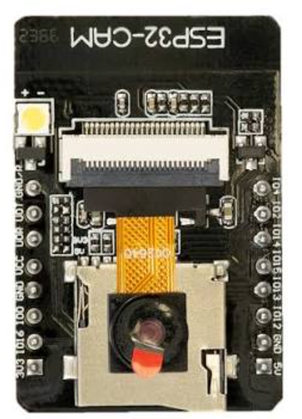
The ESP 32 CAM is a low-cost development board that features a built-in camera and Wi-Fi capabilities. It is based on the ESP32 chip, which provides powerful processing capabilities and supports various IoT applications. The board is ideal for projects involving image capture, video streaming, and remote monitoring.
Explore Projects Built with ESP 32 CAM
 Open Project in Cirkit Designer
 Open Project in Cirkit Designer
 Open Project in Cirkit Designer
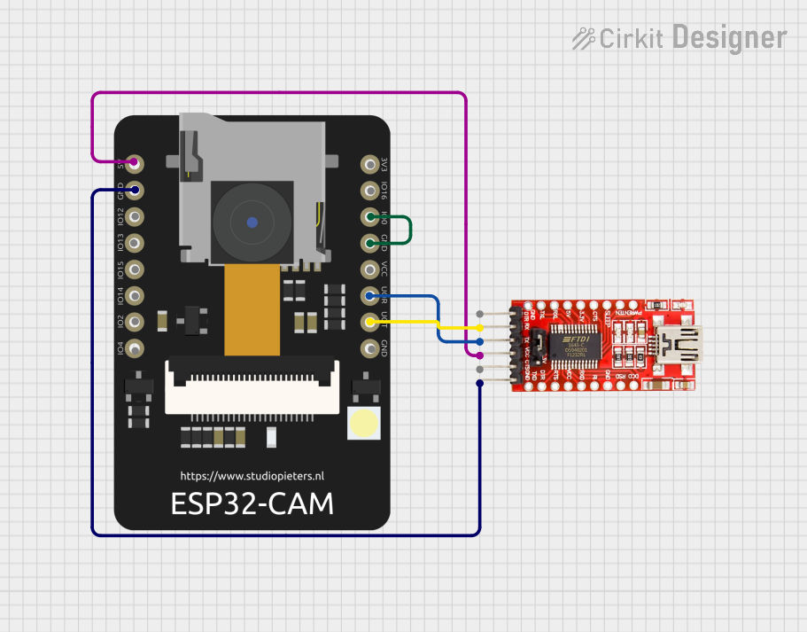 Open Project in Cirkit Designer
Explore Projects Built with ESP 32 CAM
Open Project in Cirkit DesignerOpen Project in Cirkit DesignerOpen Project in Cirkit DesignerOpen Project in Cirkit DesignerCommon Applications and Use Cases
- Home security systems with live video streaming
- IoT-based surveillance and monitoring
- Smart doorbells and facial recognition systems
- Remote-controlled robots with video feedback
- Wildlife monitoring and time-lapse photography
Technical Specifications
Key Technical Details
| Specification | Value |
|---|---|
| Microcontroller | ESP32 Dual-Core Processor |
| Camera Module | OV2640 (2MP) |
| Flash Memory | 4 MB (PSRAM) |
| Wi-Fi | 802.11 b/g/n |
| Bluetooth | BLE and Bluetooth 4.2 |
| Operating Voltage | 3.3V |
| Input Voltage Range | 5V (via micro-USB or external power) |
| GPIO Pins | 9 (including UART, SPI, I2C, PWM support) |
| Dimensions | 27mm x 40.5mm |
Pin Configuration and Descriptions
| Pin Name | Description |
|---|---|
| 3.3V | Power input pin (3.3V supply) |
| GND | Ground pin |
| GPIO0 | Used for boot mode selection (connect to GND for programming mode) |
| GPIO1 | UART TX pin (used for serial communication) |
| GPIO3 | UART RX pin (used for serial communication) |
| GPIO12 | General-purpose I/O pin |
| GPIO13 | General-purpose I/O pin |
| GPIO14 | General-purpose I/O pin |
| GPIO15 | General-purpose I/O pin |
| GPIO16 | General-purpose I/O pin |
| GPIO33 | General-purpose I/O pin |
| RESET | Reset pin (used to restart the board) |
Usage Instructions
How to Use the ESP 32 CAM in a Circuit
Powering the Board:
- Use a 5V power supply via the micro-USB port or connect a 5V source to the
5Vpin. - Ensure the
GNDpin is connected to the ground of your circuit.
- Use a 5V power supply via the micro-USB port or connect a 5V source to the
Programming the Board:
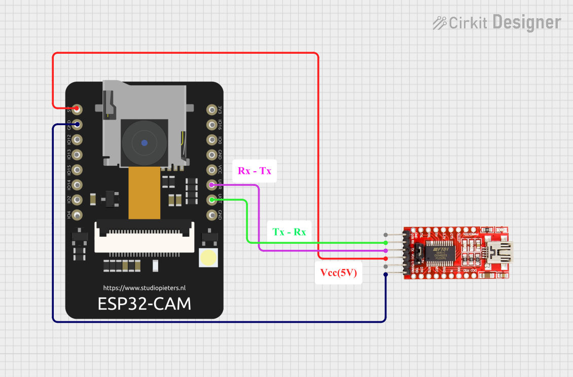
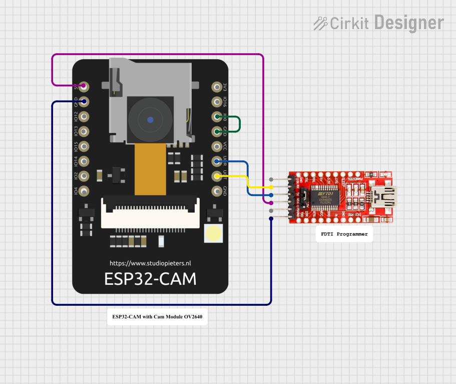
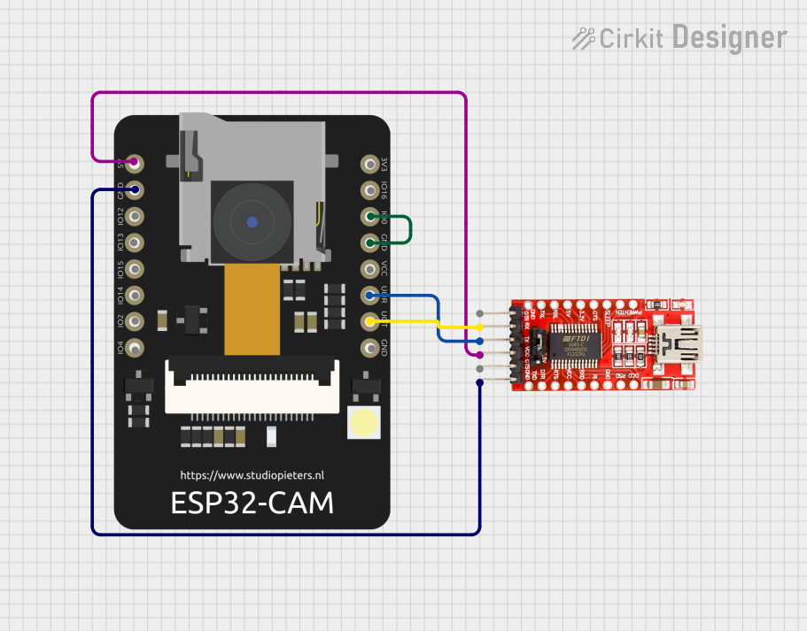
- Connect the ESP 32 CAM to your computer using a USB-to-TTL converter.
- Connect the
TXpin of the converter toGPIO1(UART TX) and theRXpin toGPIO3(UART RX). - Short the
GPIO0pin toGNDto enable programming mode. - Use the Arduino IDE or ESP-IDF to upload your code.
Connecting the Camera:
- The OV2640 camera module is pre-attached to the board. Ensure it is securely connected to the camera port.
Wi-Fi Configuration:
- Use the ESP32's built-in Wi-Fi capabilities to connect to a network.
- Configure the SSID and password in your code for network access.
Important Considerations and Best Practices
- Power Supply: Ensure a stable 5V power source to avoid unexpected resets or malfunctions.
- Heat Management: The ESP 32 CAM can get warm during operation. Consider adding a heatsink for prolonged use.
- Antenna Placement: For optimal Wi-Fi performance, ensure the onboard antenna is not obstructed by metal objects.
- Boot Mode: Always disconnect the
GPIO0pin fromGNDafter programming to boot into normal mode.
Example Code for Arduino IDE
Below is an example code to set up the ESP 32 CAM for video streaming:
#include <WiFi.h>
#include "esp_camera.h"

// Replace with your network credentials
const char* ssid = "Your_SSID";
const char* password = "Your_PASSWORD";

// Camera configuration
#define PWDN_GPIO_NUM    -1
#define RESET_GPIO_NUM   -1
#define XCLK_GPIO_NUM     0
#define SIOD_GPIO_NUM    26
#define SIOC_GPIO_NUM    27
#define Y9_GPIO_NUM      35
#define Y8_GPIO_NUM      34
#define Y7_GPIO_NUM      39
#define Y6_GPIO_NUM      36
#define Y5_GPIO_NUM      21
#define Y4_GPIO_NUM      19
#define Y3_GPIO_NUM      18
#define Y2_GPIO_NUM       5
#define VSYNC_GPIO_NUM   25
#define HREF_GPIO_NUM    23
#define PCLK_GPIO_NUM    22

void startCameraServer();

void setup() {
  Serial.begin(115200);
  WiFi.begin(ssid, password);

  // Wait for Wi-Fi connection
  while (WiFi.status() != WL_CONNECTED) {
    delay(500);
    Serial.print(".");
  }
  Serial.println("");
  Serial.println("WiFi connected");
  Serial.println(WiFi.localIP());

  // Camera initialization
  camera_config_t config;
  config.ledc_channel = LEDC_CHANNEL_0;
  config.ledc_timer = LEDC_TIMER_0;
  config.pin_d0 = Y2_GPIO_NUM;
  config.pin_d1 = Y3_GPIO_NUM;
  config.pin_d2 = Y4_GPIO_NUM;
  config.pin_d3 = Y5_GPIO_NUM;
  config.pin_d4 = Y6_GPIO_NUM;
  config.pin_d5 = Y7_GPIO_NUM;
  config.pin_d6 = Y8_GPIO_NUM;
  config.pin_d7 = Y9_GPIO_NUM;
  config.pin_xclk = XCLK_GPIO_NUM;
  config.pin_pclk = PCLK_GPIO_NUM;
  config.pin_vsync = VSYNC_GPIO_NUM;
  config.pin_href = HREF_GPIO_NUM;
  config.pin_sscb_sda = SIOD_GPIO_NUM;
  config.pin_sscb_scl = SIOC_GPIO_NUM;
  config.pin_pwdn = PWDN_GPIO_NUM;
  config.pin_reset = RESET_GPIO_NUM;
  config.xclk_freq_hz = 20000000;
  config.pixel_format = PIXFORMAT_JPEG;

  if (psramFound()) {
    config.frame_size = FRAMESIZE_UXGA;
    config.jpeg_quality = 10;
    config.fb_count = 2;
  } else {
    config.frame_size = FRAMESIZE_SVGA;
    config.jpeg_quality = 12;
    config.fb_count = 1;
  }

  // Initialize the camera
  esp_err_t err = esp_camera_init(&config);
  if (err != ESP_OK) {
    Serial.printf("Camera init failed with error 0x%x", err);
    return;
  }

  // Start the camera server
  startCameraServer();
  Serial.println("Camera ready! Use the IP address to connect.");
}

void loop() {
  // Main loop does nothing; camera server handles requests
}
Troubleshooting and FAQs
Common Issues and Solutions
The ESP 32 CAM is not detected by the computer:
- Ensure the USB-to-TTL converter is properly connected.
- Verify that the
GPIO0pin is connected toGNDduring programming.
Wi-Fi connection fails:
- Double-check the SSID and password in your code.
- Ensure the Wi-Fi network is within range and not overloaded.
Camera initialization fails:
- Verify that the camera module is securely connected to the board.
- Check the camera configuration in your code for any incorrect pin assignments.
Video stream is slow or laggy:
- Reduce the frame size or increase the JPEG quality setting in the code.
- Ensure a strong and stable Wi-Fi connection.
FAQs
Can I use the ESP 32 CAM without a camera module?
Yes, the board can still be used for other IoT applications without the camera.What is the maximum resolution supported by the camera?
The OV2640 camera supports a maximum resolution of 1600x1200 (UXGA).Can the ESP 32 CAM be powered by batteries?
Yes, it can be powered by a 3.7V LiPo battery with a suitable voltage regulator.Is the ESP 32 CAM compatible with Arduino IDE?
Yes, the ESP 32 CAM can be programmed using the Arduino IDE with the appropriate board package installed.